12. Timer (Three-phase Motor Control Timer Function)
puorG92/C61M
page 129
854fo7002,03.raM21.1.veR
2110-1010B90JER
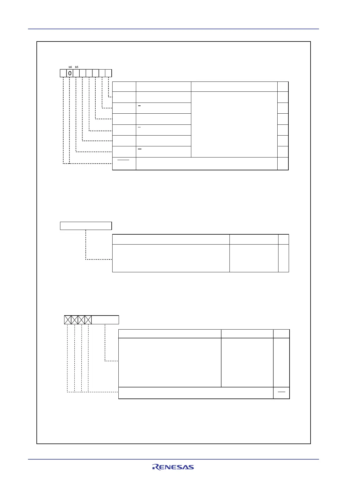
Figure 12.28 IDB0 Register, IDB1Register, DTT Register, and ICTB2 Register
Three-phase
utput Buffer Re
ister(i=0,1)
(1)
Symbol Address After Reset
IDB0 034A
16 001111112
IDB1 034B
16 001111112
RW
RW
RW
RWBit Name FunctionBit Symbol
DUi
DUBi
DVi
U phase output buffer i
NOTE:
1. Registers IDB0 and IDB1 values are transferred to the three-phase shift register by a transfer trigger. The value
written to the IDB0 register aftera transfer trigger represents the output signal of each phase, and the next value
written to the IDB1 register at the falling edge of the timer A1, A2, or A4 one-shot pulse represents the output signal
of each phase.
(b7-b6)
RW
DVBi
Nothing is assigned. If necessary, set to 0. When read,
these contents are 0
Write the output level
0: Active level
1: Inactive level
When read, these bits show the three-phase
output shift register value.
DWi
DWBi
RW
RW
U phase output buffer i
V phase output buffer i
V phase output buffer i
W phase output buffer i
W phase output buffer i
7
4
2b1b0
Dead Time Timer
(1, 2)
Symbol Address After Reset
DTT 034C
16 Undefined
WO
RWFunction Setting Range
NOTES:
1. Use MOV instruction to write to this register.
2. Effective when the INV15 bit is set to 0 (dead time timer enable). If the INV15 bit is set to 1, the dead time timer is
disabled and has no effect.
1 to 255
b7 b0
Assuming the set value = n, upon a start trigger the timer starts
counting the count souce selected by the INV12 bit and stops
after counting it n times. The positive or negative phase
whichever is going from an inactive to an active level changes
at the same time the dead time timer stops.
RO
Timer B2 Interrupt Occurrences Frequency Set Counter
Symbol
ICTB2
Address
034D
16
After Reset
Undefined
Function
Setting Range
b7 b6 b5 b4 b0
If the INV01 bit is 0 (ICTB2 counter counted every
time timer B2 underflows), assuming the set value
= n, a timer B2 interrupt is generated at every nth
occurrence of a timer B2 underflow.
If the INV01 bit is 1 (ICTB2 counter count timing
selected by the INV00 bit), assuming the set value
= n, a timer B2 interrupt is generated at every nth
occurrence of a timer B2 underflow that meets the
condition selected by the INV00 bit.
1 to 15
NOTE:
1. Use MOV instruction to write to this register.
If the INV01 bit is set to 1, make sure the TB2S bit also is set to 0 (timer B2 count stopped) when writing to
this register. If the INV01 bit is set to 0, although this register can be written even when the TB2S bit is set to
1 (timer B2 count start), do not write synchronously with a timer B2 underflow.
RW
WO
(1)
Nothing is assigned. When write, set to "0". When read, the content is
undefined.
b3
 Loading...


