12. Timer (Three-phase Motor Control Timer Function)
puorG92/C61M
page 135
854fo7002,03.raM21.1.veR
2110-1010B90JER
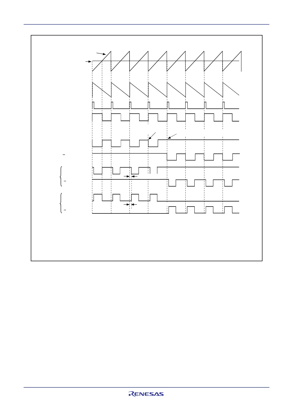
Figure 12.34 Sawtooth Wave Modulation Operation
Timer B2
U phase
Sawtooth wave
Signal wave
U phase
output signal
(1)
U phase
U phase
output signal
(1)
U phase
U phase
INV14 = 0
Sawtooth Waveform as a Carrier Wave
INV14 = 1
NOTE:
1. Internal signals. See Figure 12.25.
The above applies under the following conditions:
INVC0 = 01XX110X
2 (X varies depending on each system) and INVC1 = 010XXX002.
Examples of PWM output change are:
• Default value of registers IDB0 and IDB1: DU0=0, DUB0=1, DU1=1, DUB1=1.
They are changed to DU0=1, DUB0=0, DU1=1, DUB1=1 when the timer B2 interrupt is generated.
Start trigger signal
for timer A4
(1)
Timer A4
one-shot pulse
(1)
Dead time
Dead time
(“H” active)
(“L” active)
Transfer the values to the three-
phase output shift register
Rewrite registers
IDB0 and IDB1
 Loading...


