14. Serial I/O
puorG92/C61M
page 175
854fo7002,03.raM21.1.veR
2110-1010B90JER
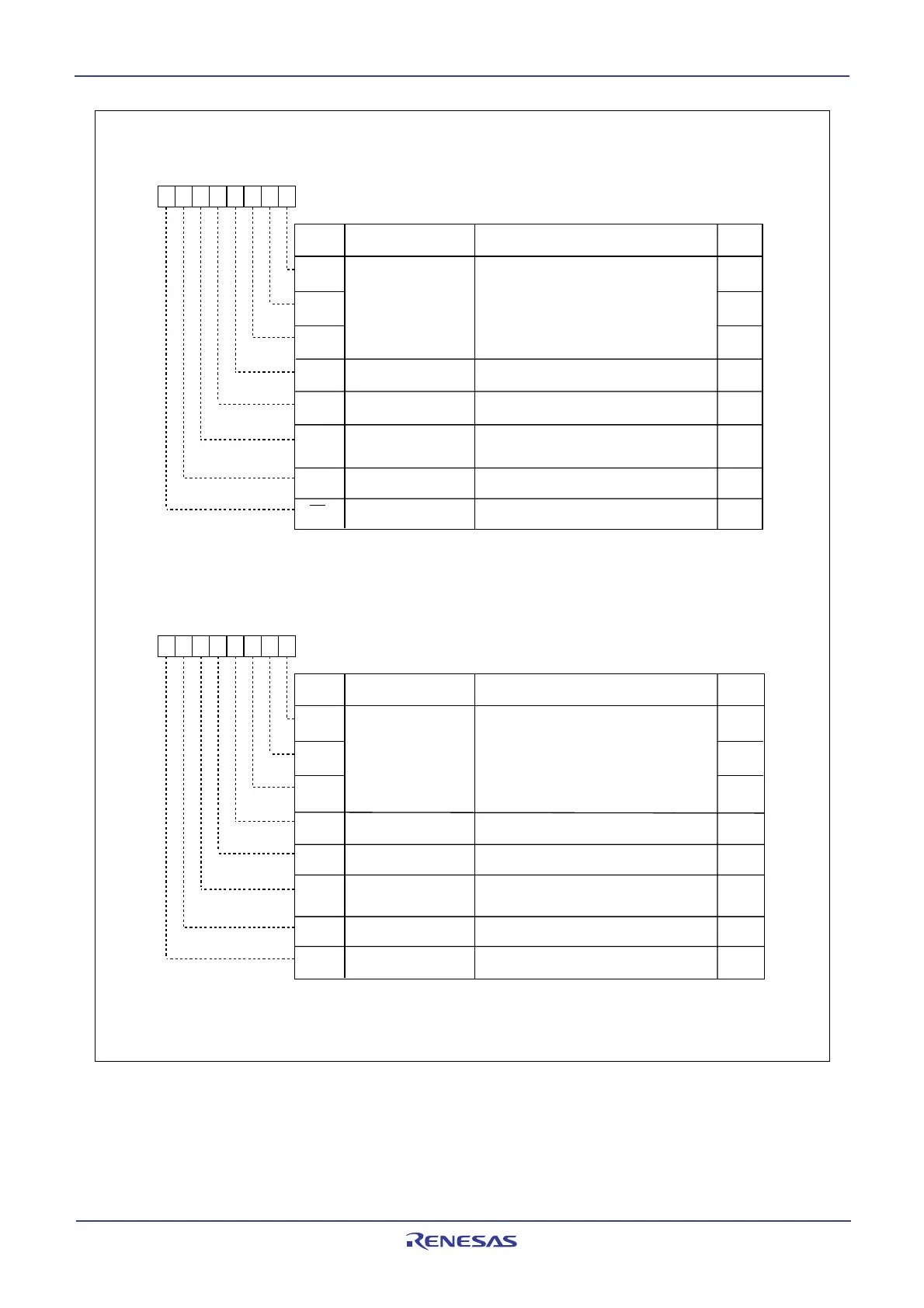
Figure 14.5 U0MR to U2MR Registers
UARTi Transmit/receive Mode Register (i=0, 1)
b7 b6 b5 b4 b3 b2 b1 b0
Bit Name
Bit
Symbol
CKDIR
SMD1
SMD0
Serial I/O mode select bit
(2)
SMD2
Internal/external clock
select bit
STPS
PRY
PRYE
(b7)
Parity enable bit
0 : Internal clock
1 : External clock
(1)
Stop bit length select bit
Odd/even parity select bit
Reserve bit
0 : One stop bit
1 : Two stop bits
0 : Parity disabled
1 : Parity enabled
b2 b1 b0
Effective when PRYE = 1
0 : Odd parity
1 : Even parity
Set to 0
Function
RW
RW
RW
RW
RW
RW
RW
RW
RW
UART2 Transmit/receive Mode Register
b7 b6 b5 b4 b3 b2 b1 b0
Bit Name
Bit
Symbol
CKDIR
SMD1
SMD0
Serial I/O mode select bit
(2)
SMD2
Internal/external clock
select bit
STPS
PRY
PRYE
IOPOL
Parity enable bit
0 : Internal clock
1 : External clock
(1)
Stop bit length select bit
Odd/even parity select bit
TxD, RxD I/O polarity
reverse bit
0 : One stop bit
1 : Two stop bits
0 : Parity disabled
1 : Parity enabled
b2 b1 b0
Effective when PRYE = 1
0 : Odd parity
1 : Even parity
0 : No reverse
1 : Reverse
Function
RW
RW
RW
RW
RW
RW
RW
RW
RW
0
Symbol Address After Reset
U2MR 0378
16 0016
NOTES:
1. Set the corresponding port direction bit for each CLKi pin to 0 (input mode).
2. To receive data, set the corresponding port direction bit for each RxDi pin to 0.
Symbol Address After Reset
U0MR, U1MR 03A0
16, 03A816 0016
NOTES:
1. Set the corresponding port direction bit for each CLK2 pin to 0 (input mode).
2. To receive data, set the corresponding port direction bit for each RxD2 pin to 0 (input mode).
3. Set the corresponding port direction bit for SCL
2 and SDA2 pins to 0 (input mode).
0 0 0 : Serial I/O disabled
0 0 1 : Clock synchronous serial I/O mode
0 1 0 : I
2
C bus mode(3)
1 0 0 : UART mode transfer data 7 bit long
1 0 1 : UART mode transfer data 8 bit long
1 1 0 : UART mode transfer data 9 bits long
Do not set the value other than the above
0 0 0 : Serial I/O disabled
0 0 1 : Clock synchronous serial I/O mode
1 0 0 : UART mode transfer data 7 bit long
1 0 1 : UART mode transfer data 8 bit long
1 1 0 : UART mode transfer data 9 bit long
Do not set the value other than the above
 Loading...


