14. Serial I/O
puorG92/C61M
page 187
854fo7002,03.raM21.1.veR
2110-1010B90JER
_______ _______
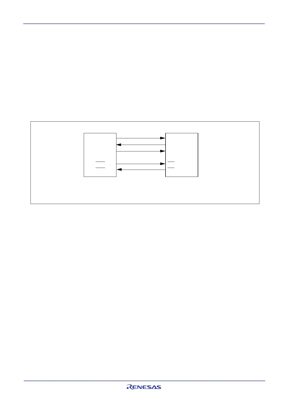
14.1.1.7 CTS/RTS separate function (UART0)
_______ _______ _______ _______
This function separates CTS0/RTS0, outputs RTS0 from the P60 pin, and accepts as input the CTS0
from the P64 pin or P70 pin. To use this function, set the register bits as shown below.
_______ _______
• The CRD bit in the U0C0 register is set to 0 (enables UART0 CTS/RTS)
_______
• The CRS bit in the U0C0 register is set to 1 (outputs UART0 RTS)
_______ _______
• The CRD bit in the U1C0 register is set to 0 (enables UART1 CTS/RTS)
_______
• The CRS bit in the U1C0 register is set to 0 (inputs UART1 CTS)
_______
• The RCSP bit in the UCON register is set to 1 (inputs CTS0 from the P64 pin or P70 pin)
• The CLKMD1 bit in the UCON register is set to 0 (CLKS1 not used)
_______ _______ _______ _______
Note that when using the CTS/RTS separate function, UART1 CTS/RTS separate function cannot be
used.
Figure 14.15 CTS/RTS separate function usage
MCU
T
X
D
0
(P6
3
)
CLK
0
(P6
1
)
CTS
0
(P6
4
)
IC
IN
OUT
CLK
RXD
0
(P6
2
)
RTS
0
(P6
0
)CTS
RTS
NOTE:
1. This applies to the case where the U1MAP bit in the PACR register is set to 0 (P6
7 to P64).
 Loading...


