14. Serial I/O
puorG92/C61M
page 198
854fo7002,03.raM21.1.veR
2110-1010B90JER
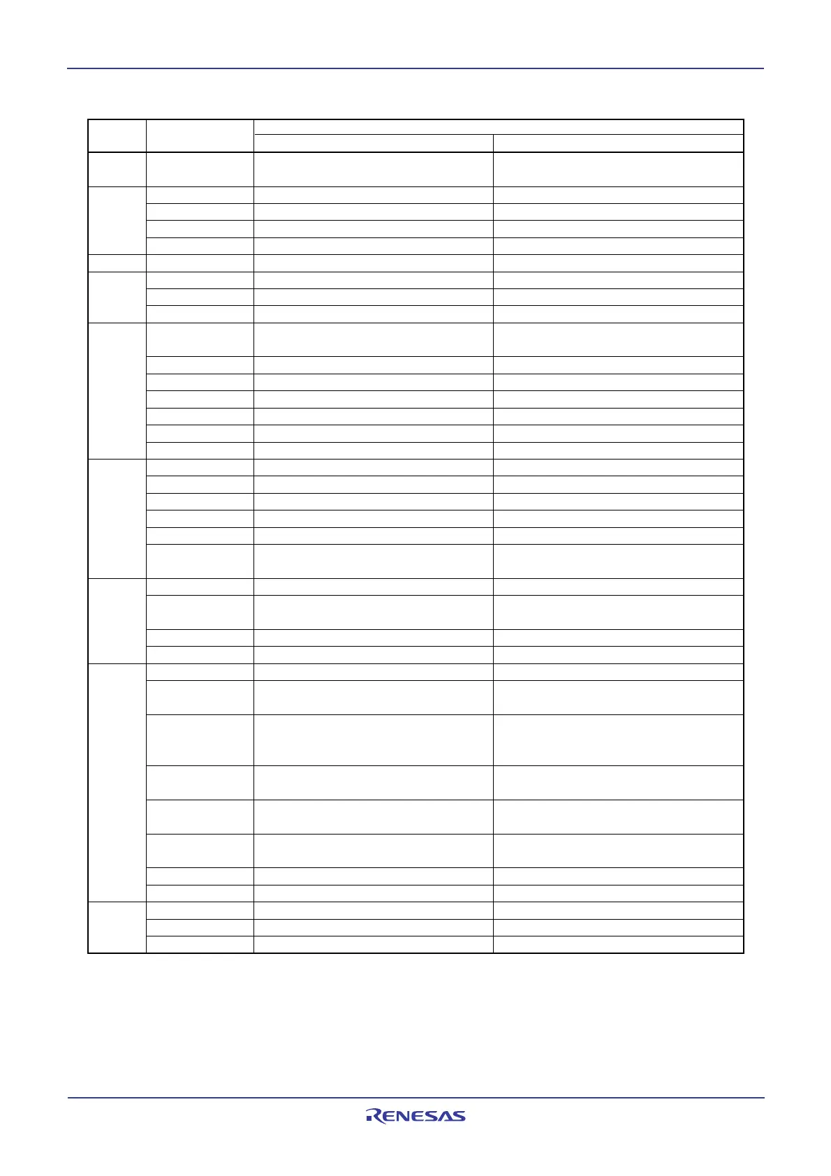
Table 14.11 Registers to Be Used and Settings in I
2
C bus mode (1) (Continued)
Register Bit Function
Master Slave
U2TB 0 to 7 Set transmission data Set transmission data
U2RB
(1)
0 to 7 Reception data can be read Reception data can be read
8 ACK or NACK is set in this bit ACK or NACK is set in this bit
ABT Arbitration lost detection flag Invalid
OER Overrun error flag Overrun error flag
U2BRG 0 to 7 Set bit rate Invalid
U2MR
(1)
SMD2 to SMD0 Set to 0102 Set to 0102
CKDIR Set to 0 Set to 1
IOPOL Set to 0 Set to 0
U2C0 CLK1, CLK0 Select the count source for the U2BRG Invalid
register
CRS Invalid because CRD = 1 Invalid because CRD = 1
TXEPT Transmit buffer empty flag Transmit buffer empty flag
CRD Set to 1 Set to 1
NCH Set to 1 Set to 1
CKPOL Set to 0 Set to 0
UFORM Set to 1 Set to 1
U2C1 TE Set this bit to 1 to enable transmission Set this bit to 1 to enable transmission
TI Transmit buffer empty flag Transmit buffer empty flag
RE Set this bit to 1 to enable reception Set this bit to 1 to enable reception
RI Reception complete flag Reception complete flag
U2IRS Invalid Invalid
U2RRM, Set to 0 Set to 0
U2LCH, U2ERE
U2SMR IICM Set to 1 Set to 1
ABC Select the timing at which arbitration-lost Invalid
is detected
BBS Bus busy flag Bus busy flag
3 to 7 Set to 0 Set to 0
U2SMR2 IICM2 Refer to Table 14.13 Refer to Table 14.13
CSC Set this bit to 1 to enable clock Set to 0
synchronization
SWC Set this bit to 1 to have SCL
2 output Set this bit to 1 to have SCL2 output
fixed to L at the falling edge of the 9th fixed to “L” at the falling edge of the 9
th
bit of clock bit of clock
ALS Set this bit to 1 to have SDA
2 output Set to 0
stopped when arbitration-lost is detected
STAC Set to 0 Set this bit to 1 to initialize UART2 at
start condition detection
SWC2 Set this bit to 1 to have SCL2 output Set this bit to 1 to have SCL2 output
forcibly pulled low forcibly pulled low
SDHI Set this bit to 1 to disable SDA2 output Set this bit to 1 to disable SDA2 output
7 Set to 0 Set to 0
U2SMR3 0, 2, 4 and NODC Set to 0 Set to 0
CKPH Refer to Table 14.13 Refer to Table 14.13
DL2 to DL0 Set the amount of SDA2 digital delay Set the amount of SDA2 digital delay
NOTE:
1. Not all bits in the register are described above. Set those bits to 0 when writing to the registers in I
2
C bus mode.
 Loading...


