14. Serial I/O
puorG92/C61M
page 199
854fo7002,03.raM21.1.veR
2110-1010B90JER
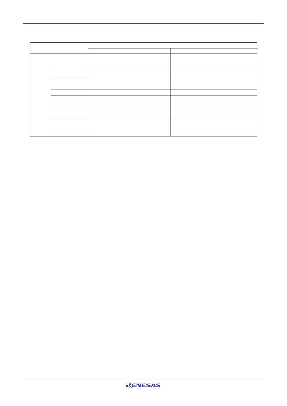
U2SMR4 STAREQ Set this bit to 1 to generate start Set to 0
condition
RSTAREQ Set this bit to 1 to generate restart Set to 0
condition
STPREQ Set this bit to 1 to generate stop Set to 0
condition
STSPSEL Set this bit to 1 to output each condition Set to 0
ACKD Select ACK or NACK Select ACK or NACK
ACKC Set this bit to 1 to output ACK data Set this bit to 1 to output ACK data
SCLHI Set this bit to 1 to have SCL2 output Set to 0
stopped when stop condition is detected
SWC9 Set to 0 Set this bit to 1 to set the SCL
2 to “L”
hold at the falling edge of the 9th bit of
clock
Register Bit Function
Master Slave
Table 14.12 Registers to Be Used and Settings in I
2
C bus Mode (2) (Continued)
NOTE:
1: Not all bits in the register are described above. Set those bits to 0 when writing to the registers in I
2
C bus mode.
 Loading...


