16. MULTI-MASTER I
2
C bus INTERFACE
puorG92/C61M
page 255
854fo7002,03.raM21.1.veR
2110-1010B90JER
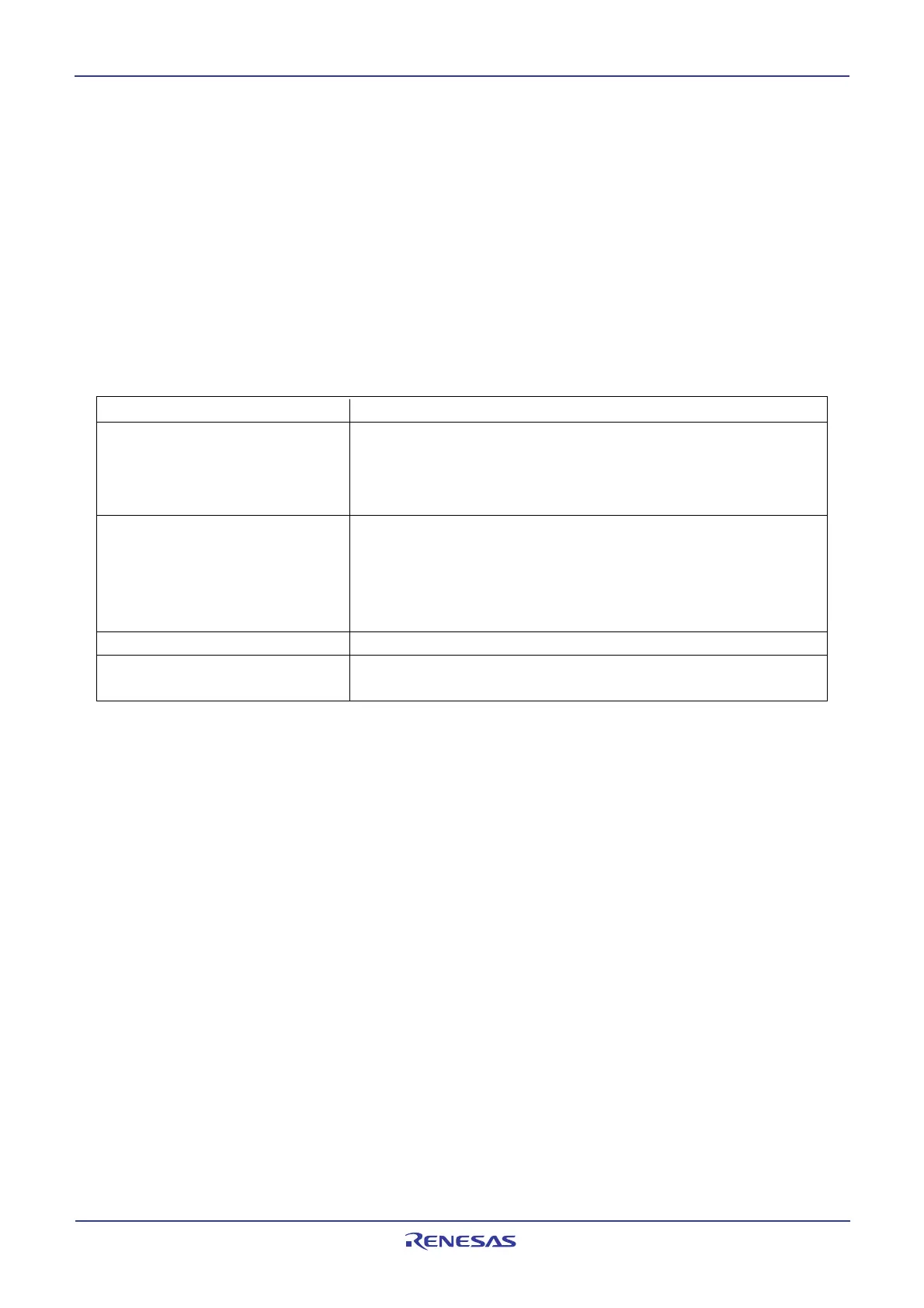
Item Function
Format Based on Philips I
2
C bus standard:
7-bit addressing format
High-speed clock mode
Standard clock mode
Communication mode Based on Philips I
2
C bus standard:
Master transmit
Master receive
Slave transmit
Slave receive
SCL clock frequency 16.1kHz to 400kHz (at VIIC
(1)
= 4MHz)
I/O pin Serial data line SDAMM(SDA)
Serial clock line SDLMM(SCL)
16. Multi-master I
2
C bus Interface
The multi-master I
2
C bus interface is a serial communication circuit based on Philips I
2
C bus data transfer
format, equipped with arbitration lost detection and synchronous functions. Figure 16.1 shows a block
diagram of the multi-master I
2
C bus interface and Table 16.1 lists the multi-master I
2
C bus interface func-
tions.
The multi-master I
2
C bus interface consists of the S0D0 register, the S00 register, the S20 register, the
S3D0 register, the S4D0 register, the S10 register, the S2D0 register and other control circuits.
Figures 16.2 to 16.8 show the registers associated with the multi-master I
2
C bus.
Table 16.1 Multi-master I
2
C bus interface functions
NOTE:
1. VIIC=I
2
C system clock
 Loading...


