17. CAN Module
puorG92/C61M
page 293
854fo7002,03.raM21.1.veR
2110-1010B90JER
Figure 17.7 C0CTLR Register
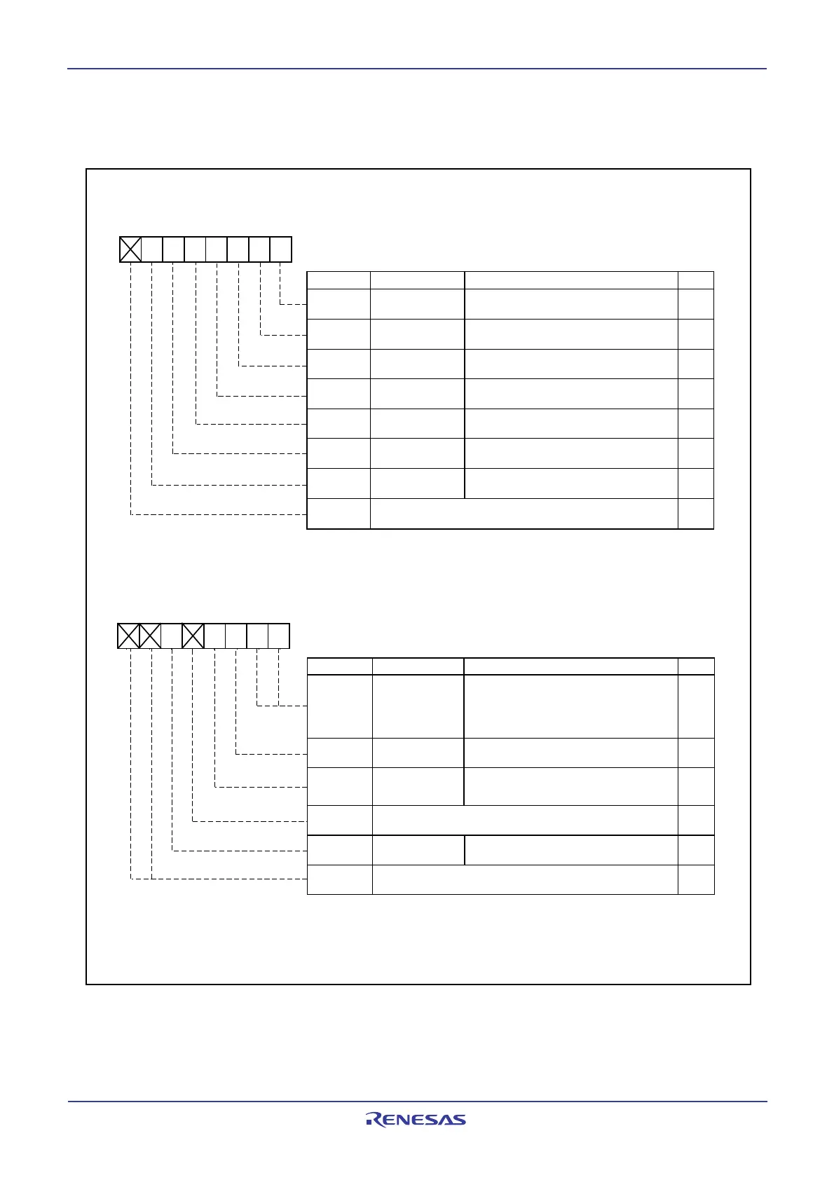
17.1.3.2 C0CTLR Register
Figure 17.7 shows the C0CTLR register.
Bit Symbol Bit Name Function
Reset
CAN module
reset bit (Note 1)
Loop back mode
LoopBack
select bit
(2)
Message order
MsgOrder
BasicCAN
Basic CAN mode
select bit
(2)
select bit
(2)
BusErrEn
Bus error interrupt
enable bit
(2)
Sleep
Sleep mode
select bit
(2, 3)
CAN port enable bit
(2, 3)
PortEn
-
(b7)
CAN0 Control Register
Symbol Address After reset
C0CTLR X0000001
2
021016
b7 b6 b5 b4 b3 b2 b1 b0
NOTES:
1. When the Reset bit is set to 1 (CAN reset/initialization mode), check that the State_Reset bit in the C0STR register is set to 1 (Reset mode).
2. Change this bit only in the CAN reset/initialization mode.
3. When using CAN0 wake-up interrupt, set these bits to 1.
4. When the PortEn bit is set to 1, set the PD9_2 bit in the PD9 register to 0.
RW
RW
RW
RW
RW
RW
RW
RW
-
0: Operation mode
1: Reset/initialization mode
0: Word access
1: Byte access
0: Basic CAN mode disabled
1: Basic CAN mode enabled
0: Loop back mode disabled
1: Loop back mode enabled
0: Bus error interrupt disabled
1: Bus error interrupt enabled
0: Sleep mode disabled
1: Sleep mode enabled; clock supply stopped
0: I/O port function
1: CTx/CRx function
(4)
(b15) (b8)
b7 b6 b5 b4 b3 b2 b1 b0
Bit Symbol Bit Name Function
TSPreScale
Bit1, Bit0
TSReset
RXOnly
RetBusOff
Nothing is assigned. If necessary, set to 0.
When read, the content is undefined
Nothing is assigned. If necessary, set to 0.
When read, the content is undefined
XX0X0000
2
Symbol Address After reset
C0CTLR 0211
16
b1 b0
NOTES:
1. When the TSReset bit is set to 1, the C0TSR register is set to 0000
16
. After this, the bit is automatically set to 0.
2. When the RetBusOff bit is set to 1, registers C0RECR and C0TECR are set to 00
16
. After this, the bit is automatically set to 0.
3. Change this bit only in the CAN reset/initialization mode.
4. When the listen-only mode is selected, do not request the transmission.
RW
RW
RW
RW
-
RW
-
0 0: Period of 1 bit time
0 1: Period of 1/2 bit time
1 0: Period of 1/4 bit time
1 1: Period of 1/8 bit time
0: In an idle state
1: Force reset of the time stamp counter
0: Listen-only mode disabled
1: Listen-only mode enabled
(4)
0: In an idle state
1: Force return from bus off
Time stamp
prescaler
(3)
Time stamp counter
reset bit
(1)
Return from bus off
command bit
(2)
Listen-only mode
select bit
(3)
Nothing is assigned. If necessary, set to 0.
When read, the content is undefined
-
(b4)
-
(b7-b6)
 Loading...


