17. CAN Module
puorG92/C61M
page 294
854fo7002,03.raM21.1.veR
2110-1010B90JER
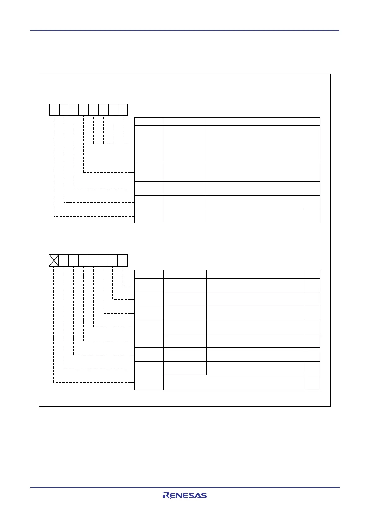
Figure 17.8 C0STR Register
17.1.3.3 C0STR Register
Figure 17.8 shows the C0STR register.
(b15) (b8)
b7 b6 b5 b4 b3 b2 b1 b0
Bit Symbol Bit Name Function
Reset state flag
Loop back state flag
Message order
state flag
Basic CAN mode
state flag
Bus error
state flag
Error passive
state flag
Error bus off
state flag
0: Operation mode
1: Reset mode
0: Word access
1: Byte access
0: Basic CAN mode disabled
1: Basic CAN mode enabled
0: No error has occurred.
1: A CAN bus error has occurred.
0: Loop back mode disabled
1: Loop back mode enabled
0: The CAN module is not in error passive state.
1: The CAN module is in error passive state.
0: The CAN module is not in error bus off state.
1: The CAN module is in error bus off state.
Nothing is assigned. If necessary, set to 0.
When read, the content is undefined
RW
RO
RO
RO
RO
RO
RO
RO
-
Symbol Address
C0STR 0213
16
X00000012
After Reset
CAN0 Status Register
NOTE:
1. These bits can be changed only when a slot which an interrupt is enabled by the C0ICR register is transmitted or received successfully.
b7 b6 b5 b4 b3 b2 b1 b0
Bit Symbol Bit Name Function
Active slot bits
(1)
b3 b2 b1 b0
RW
RO
RO
RO
RO
RO
Successful reception
flag
(1)
Transmission flag
(Transmitter)
Reception flag
(Receiver)
0 0 0 0: Slot 0
0 0 0 1: Slot 1
0 0 1 0: Slot 2
.
.
.
1 1 1 0: Slot 14
1 1 1 1: Slot 15
0: No [successful] reception
1: CAN module received a message successfully
0: CAN module is idle or receiver
1: CAN module is transmitter
0: CAN module is idle or transmitter
1: CAN module is receiver
Successful
transmission flag
(1)
0: No [successful] transmission
1: The CAN module has transmitted a message
successfully
Symbol Address
C0STR 0212
16
0016
After Reset
State_Reset
State_
LoopBack
State_
MsgOrder
State_
BasicCAN
State_
BusError
State_
ErrPass
State_
BusOff
-
(b7)
MBOX
TrmSucc
RecSucc
TrmState
RecState
 Loading...


