19. Programmable I/O Ports
puorG92/C61M
page 325
854fo7002,03.raM21.1.veR
2110-1010B90JER
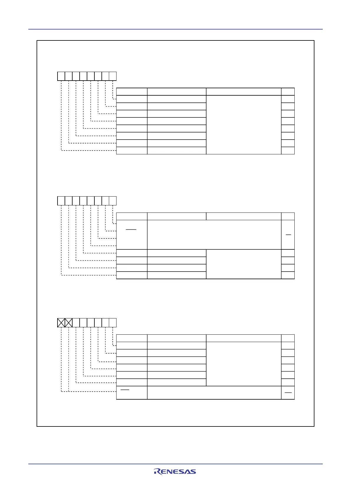
Figure 19.8 PUR0 to PUR2 Registers
Pull-up Control Register 0 (1)
Symbol Address After Reset
PUR0 03FC
16 0016
Bit Name Function Bit Symbol RW
b7 b6 b5 b4 b3 b2 b1 b0
PU00 P0
0
to P0
3
pull-up
PU01 P0
4
to P0
7
pull-up
PU02 P1
0
to P1
3
pull-up
PU03 P1
4
to P1
7
pull-up
PU04 P2
0
to P2
3
pull-up
PU05 P2
4
to P2
7
pull-up
PU06 P3
0
to P3
3
pull-up
PU07 P3
4
to P3
7
pull-up
0: Not pulled up
1: Pulled up
(1)
Pull-up Control Register 1
Symbol Address After Reset
PUR1 03FD
16 0016
Bit Name Function Bit Symbol
b7 b6 b5 b4 b3 b2 b1 b0
PU14 P6
0
to P6
3
pull-up
PU15 P6
4
to P6
7
pull-up
PU16 P7
0
to P7
3
pull-up
PU17 P7
4
to P7
7
pull-up
0: Not pulled high
1: Pulled high
(1)
NOTE:
1. The pin for which this bit is 1 (pulled up) and the direction bit is 0 (input mode) is pulled up.
RW
RW
RW
RW
RW
RW
RW
RW
RW
RW
RW
RW
RW
NOTE:
1. The pin for which this bit is 1 (pulled up) and the direction bit is 0 (input mode) is pulled up.
Pull-up Control Register 2
Symbol Address After Reset
PUR2 03FE
16 0016
Bit Name
FunctionBit Symbol
b7 b6 b5 b4 b3 b2 b1 b0
PU20 P8
0
to P8
3
pull-up
PU21 P8
4
to P8
7
pull-up
PU22 P9
0
to P9
3
pull-up
PU23 P9
5
to P9
7
pull-up
PU24 P10
0
to P10
3
pull-up
PU25 P10
4
to P10
7
pull-up
Nothing is assigned. If necessary, set to 0.
When read, the content is 0
0: Not pulled up
1: Pulled up
(1)
RW
RW
RW
RW
RW
RW
RW
(b7-b6)
NOTE:
1. The pin for which this bit is 1 (pulled up) and the direction bit is 0 (input mode) is pulled up.
Nothing is assigned. If necessary, set to 0.
When read, the content is 0
(b3-b0)
 Loading...


