21. Electrical Characteristics (Normal-version)
puorG92/C61M
page 374
854fo7002,03.raM21.1.veR
2110-1010B90JER
VCC = 5V
Timing Requirements
(VCC = 5V, VSS = 0V, at Topr = – 20 to 85
o
C / – 40 to 85
o
C unless otherwise specified)
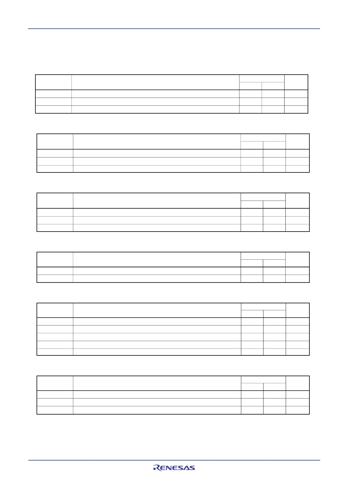
Table 21.12 Timer A Input (Gating Input in Timer Mode)
Table 21.13 Timer A Input (External Trigger Input in One-shot Timer Mode)
Table 21.14 Timer A Input (External Trigger Input in Pulse Width Modulation Mode)
Table 21.15 Timer A Input (Counter Increment/decrement Input in Event Counter Mode)
Table 21.11 Timer A Input (Counter Input in Event Counter Mode)
Table 21.16 Timer A Input (Two-phase Pulse Input in Event Counter Mode)
Standard
Max.
ns
TAi
IN input LOW pulse width
t
w(TAL)
Min.
ns
ns
Unit
TAiIN input HIGH pulse width
t
w(TAH)
ParameterSymbol
t
c(TA)
TAiIN input cycle time
40
100
40
Standard
Max.
Min.
ns
ns
ns
Unit
TAiIN input cycle time
TAi
IN input HIGH pulse width
TAi
IN input LOW pulse width
t
c(TA)
tw(TAH)
tw(TAL)
Symbol Parameter
400
200
200
Standard
Max.
Min.
ns
ns
ns
Unit
TAiIN input cycle time
TAi
IN input HIGH pulse width
TAi
IN input LOW pulse width
t
c(TA)
tw(TAH)
tw(TAL)
Symbol Parameter
200
100
100
Standard
Max.
Min.
ns
ns
Unit
tw(TAH)
tw(TAL)
Symbol Parameter
TAi
IN input HIGH pulse width
TAi
IN input LOW pulse width
100
100
Standard
Max.
Min.
ns
ns
ns
Unit
ns
ns
Symbol Parameter
TAi
OUT input cycle time
TAi
OUT input HIGH pulse width
TAi
OUT input LOW pulse width
TAi
OUT input setup time
TAi
OUT input hold time
t
c(UP)
tw(UPH)
tw(UPL)
tsu(UP-T
IN
)
th(T
IN-
UP)
2000
1000
1000
400
400
Standard
Max.
Min.
ns
ns
ns
Unit
Symbol Parameter
TAi
IN input cycle time
TAi
OUT input setup time
TAi
IN input setup time
t
c(TA)
tsu(TA
IN
-TA
OUT
)
tsu(TA
OUT
-TA
IN
)
800
200
200
 Loading...


