21. Electrical Characteristics (Normal-version)
puorG92/C61M
page 384
854fo7002,03.raM21.1.veR
2110-1010B90JER
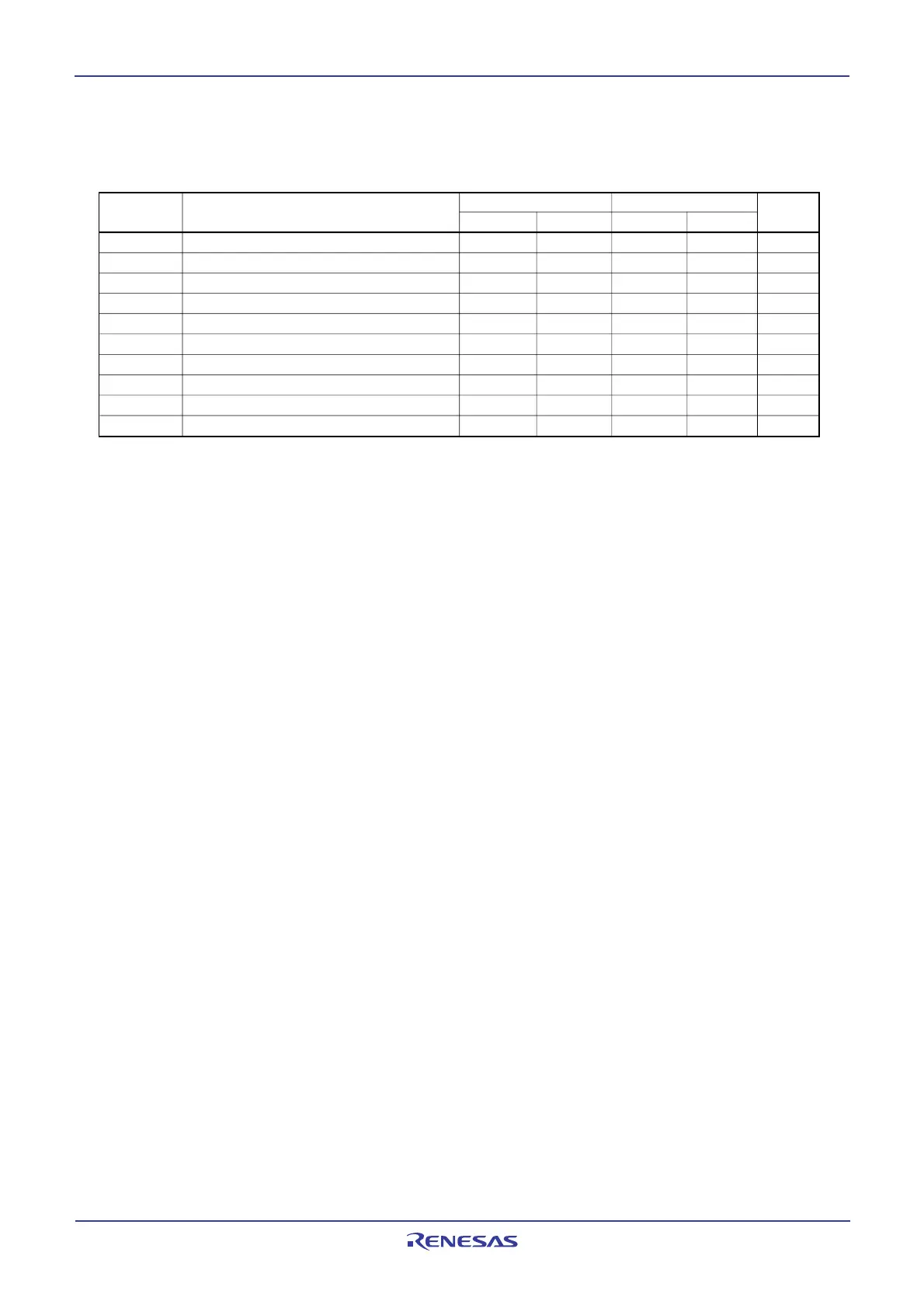
VCC = 3V
Timing Requirements
(VCC = 3V, VSS = 0V, at Topr = – 20 to 85
o
C / – 40 to 85
o
C unless otherwise specified)
Table 21.39 Multi-master I
2
C bus Line
High-speed clock mode
Max.
Min.
Bus free time
The hold time in start condition
The hold time in SCL clock 0 status
µs
µs
µs
tBUF
tHD;STA
tLOW
ParameterSymbol Unit
tR
tHIGH
tHD;DAT
ns
µs
µs
Data hold time
The hold time in SCL clock 1 status
SCL, SDA signals' rising time
1.3
0.6
1.3
0
0.6
20+0.1Cb
tF
SCL, SDA signals' falling time
t
SU;DAT
Data setup time
t
SU;STA
The setup time in restart condition
t
SU;STO
Stop condition setup time
Standard clock mode
Max.Min.
4.7
4.0
4.7
0
4.0
250
4.7
4.0
1000
300
100
0.6
20+0.1Cb
0.6
300
300
0.9
ns
ns
µs
µs
 Loading...


