A-D Converter
M30240 Group
Rev.1.00 Sep 24, 2003 Page 101 of 360
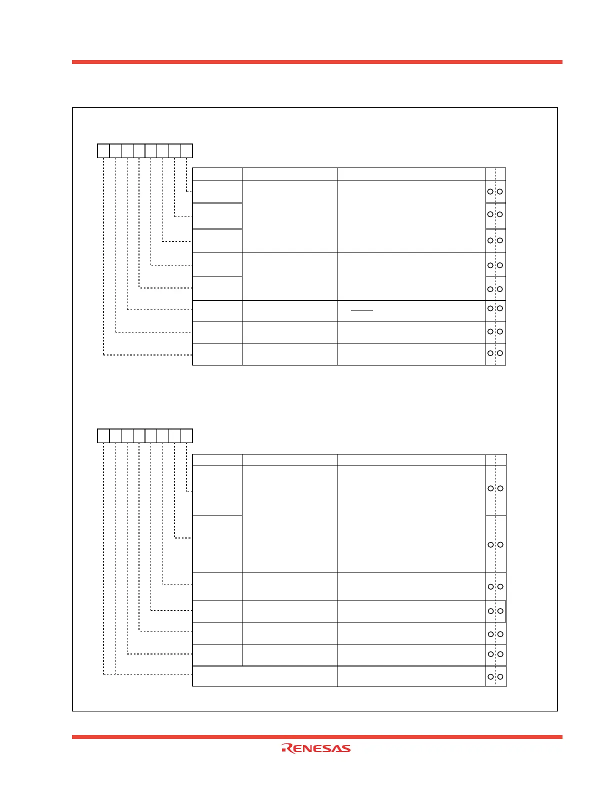
Figure 1.97: A-D converter-related registers (1)
A-D control register 0 (Note 1)
Symbol Address When reset
ADCON0 03D6
16 00000XXX2
b7 b6 b5 b4 b3 b2 b1 b0
Analog input pin select bit
0 0 0 : AN
0
is selected
0 0 1 : AN
1
is selected
0 1 0 : AN
2
is selected
0 1 1 : AN
3
is selected
1 0 0 : AN
4
is selected
1 0 1 : AN
5
is selected
1 1 0 : AN
6
is selected
1 1 1 : AN
7
is selected (Note 2)
CH0
Bit symbol Bit name Function
CH1
CH2
A-D operation mode
select bit 0
0 0 : One-shot mode
0 1 : Repeat mode
1 0 : Single sweep mode
1 1 : Repeat sweep mode 0
Repeat sweep mode 1 (Note 2)
MD0
MD1
Trigger select bit 0 : Software trigger
1 : AD
TRG
trigger
TRG
ADST
A-D conversion start flag 0 : A-D conversion disabled
1 : A-D conversion started
Frequency select bit 0 0 : f
AD
/4 is selected
1 : f
AD
/2 is selected
CKS0
WR
A-D control register 1 (Note)
Symbol Address When reset
ADCON1 03D7
16 0016
Bit name FunctionBit symbol
b7 b6 b5 b4 b3 b2 b1 b0
A-D sweep pin select bit
SCAN0
SCAN1
MD2
BITS
8/10-bit mode select bit 0 : 8-bit mode
1 : 10-bit mode
VCUT
Vref connect bit
A-D operation mode
select bit 1
0 : Any mode other than repeat sweep
mode 1
1 : Repeat sweep mode 1
0 : Vref not connected
1 : Vref connected
WR
b2 b1 b0
b4 b3
When single sweep and repeat sweep
mode 0 are selected
0 0 : AN
0
, AN
1
(2 pins)
0 1 : AN
0
to AN
3
(4 pins)
1 0 : AN
0
to AN
5
(6 pins)
1 1 : AN
0
to AN
7
(8 pins)
b1 b0
When repeat sweep mode 1 is selected
0 0 : AN
0
(1 pin)
0 1 : AN
0
, AN
1
(2 pins)
1 0 : AN
0
to AN
2
(3 pins)
1 1 : AN
0
to AN
3
(4 pins)
b1 b0
Note 1: If the A-D control register is rewritten during A-D conversion, the conversion result is
indeterminate.
Note 2: When changing A-D operation mode, set analog input pin again.
Frequency select bit 1 0 : f
AD
/2 or f
AD
/4 is selected
1 : f
AD
is selected
CKS1
Note: If the A-D control register is rewritten during A-D conversion, the conversion result is
indeterminate.
Reserved bit Always set to "0"
0
0
 Loading...


