Clock-Asynchronous Serial I/O
M30240 Group
Rev.1.00 Sep 24, 2003 Page 212 of 360
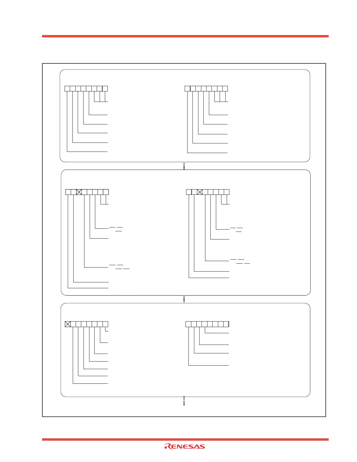
Figure 2.63: Set-up procedure of transmission in UART mode (1)
Continued to the next page
Setting UARTi transmit/receive mode register (i=0 to 2)
Internal/external clock select bit
0 : Internal clock
Stop bit length select bit
0 : One stop bit
b7 b0
01010
Odd/even parity select bit
(Valid when bit 6 = “1” )
0 : Odd parity
Parity enable bit
1 : Parity enabled
Sleep select bit
0 : Invalid
Serial I/O mode select bit
1 0 1 : Transfer data 8 bits long
b2 b1 b0
010
UART0 transmit/receive mode register
U0MR [Address 03A0
16]
UART1 transmit/receive mode register
U1MR [Address 03A8
16]
Internal/external clock select bit
0 :
b7 b0
01010
Odd/even parity select bit
(Valid when bit 6 = “1” )
0 : Odd parity
TXD, R XD I/O polarity reverse bit
Usually set to “0”
Serial I/O mode select bit
1 0 1 : Transfer data 8 bits long
b2 b1 b0
010
UART2 transmit/receive mode register
U2MR [Address 0378
16]
Setting UARTi transmit/receive control register 0 (i = 0 to 2)
UART0 transmit/receive control register 0
U0C0 [Address 03A4
16]
UART1 transmit/receive control register 0
U1C0 [Address 03AC
16]
Must be “0” in UART mode
b7 b0
0000
BRG count source select bit
0 0 : f
1 is selected
0 1 : f
8 is selected
1 0 : f
32 is selected
1 1 : Inhibited
b1 b0
CTS/RTS function select bit (Valid when bit 4 = “0”)
0 : CTS function is selected
CTS/RTS disable bit
0 : CTS/RTS function enabled
Transmit register empty flag
0 : Data present in transmit register
(during transmission)
1 : No data present in transmit register
(transmission completed)
Must be “0” in UART mode
UART2 transmit/receive control register 0
U2C0 [Address 037C
16]
Must be “0” in UART mode
b7 b0
0000
BRG count source select bit
0 0 : f
1 is selected
0 1 : f
8 is selected
1 0 : f
32 is selected
1 1 : Inhibited
b1 b0
CTS/RTS function select bit (Valid when bit 4 = “0”)
0 : CTS function is selected
CTS/RTS disable bit
0 : CTS/RTS function enabled
Transmit register empty flag
0 : Data present in transmit register
(during transmission)
1 : No data present in transmit register
(transmission completed)
Transfer format select bit
0 : LSB first
Setting UART transmit/receive control register 2 and UART2 transmit/receive control register 1
UART2transmit/receive control register 1
U2C1 [Address 037D
16]
UART0 transmit interrupt cause select bit
1 : Transmission completed (TXEPT = 1)
Data logic select bit
0 : No reverse
Error signal output enable bit
0 : output enabled
Invalid in UART mode
UART transmit/receive control register 2
UCON [Address 03B0
16]
UART0 transmit interrupt cause select bit
1 : Transmission completed (TXEPT = 1)
Must be “0” in UART mode
Stop bit length select bit
0 : One stop bit
Parity enable bit
1 : Parity enabled
UART1 transmit interrupt cause select bit
1 : Transmission completed (TXEPT = 1)
Invalid in UART mode
Invalid in UART mode
Invalid in UART mode
00
b7 b0
00
b7 b0
Reserved
Must always be "0"
Must be "0" in UART mode
1
1
1
 Loading...


