Universal Serial Bus
M30240 Group
Rev.1.00 Sep 24, 2003 Page 49 of 360
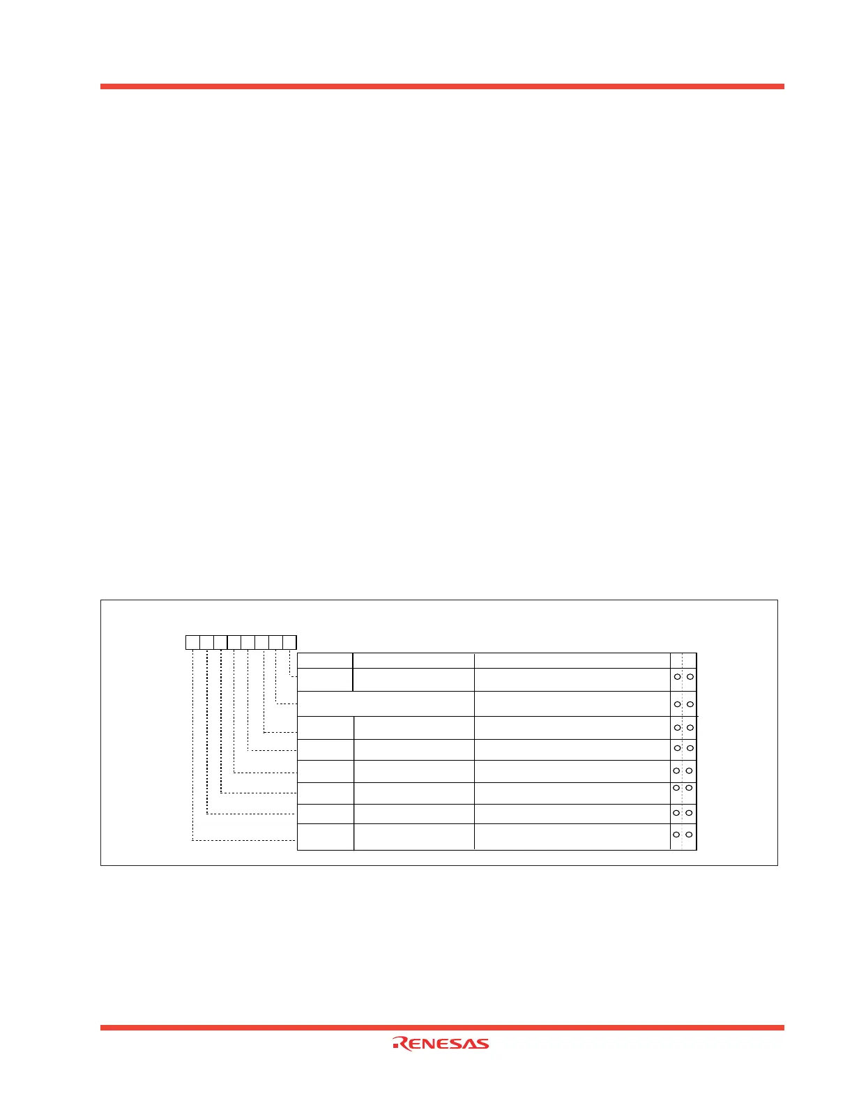
1.2.18.4.5 USB Interrupt Status Registers 1 and 2
USB Interrupt Status Registers 1 and 2, shown in Figure 1.34 and Figure 1.35, are used to indicate the con-
dition that caused a USB function interrupt and USB Reset, Suspend and Resume Interrupts to the CPU. A
“1” indicates the corresponding condition caused an interrupt. The USB Interrupt Status Register bits can be
cleared by writing a “1” to the corresponding bit.
INTST0 is set to a “1” by the USB FCU when (in Endpoint 0 CSR):
• A packet of data is successfully received (EP0CSR0 - OUT_PKT_RDY is set by the USB FCU)
• A packet of data is successfully sent (EP0CSR - IN_PKT_RDY is cleared by the USB FCU)
• EP0CSR3 (DATA_END) bit is cleared by the USB FCU
• EP0CSR4 (FORCE_STALL) bit is set by the USB FCU
• EP0CSR5 (SETUP_END) bit is set by the USB FCU
INTST2, INTST4, INTST6 or INTST8 is set to a “1” by the USB FCU when (in Endpoint x IN CSR):
• A packet of data is successfully sent (INXCSR0 - IN_PKT_RDY is cleared by the USB FCU)
• INXCSR1 (UNDER_RUN) bit is set by the USB FCU
INTST3, INTST5, INTST7 or INTST9 is set to a “1” by the USB FCU when (in Endpoint xOUT CSR):
• A packet of data is successfully received (OUTXCSR0 - OUT_PKT_RDY is set by the USB FCU)
• OUTXCSR1 (OVER_RUN) bit is set by the USB FCU
• OUTXCSR4 (FORCE_STALL) bit is set by the USB FCU
INTST12 is set to a “1” by the USB FCU when an overrun or underrun condition occurs in any of the endpoints.
INTST13 is set to a “1” by the USB FCU when a USB reset signaling from the host is received. All internal
register bits except this bit are reset to their default values when the USB reset is received.
INTST14 is set to a “1” by the USB FCU when the USB FCU is in the suspend state and non-idle signaling is
received from D+/D-.
INTST15 is set to a “1” by the USB FCU when D+/D- are in the idle state for more than 3ms.
Figure 1.34: USB Interrupt Status Register 1
USB Interrupt Status Register 1
Symbol Address When reset
USBIS1 0302
16
00
16
Bit nameBit symbol
b7 b6 b5 b4 b3 b2 b1 b0
Function
W
R
Reserved
Must always be set to "0"
INTST0
INTST2
INTST3
INTST4
INTST5
INTST6
INTST7
USB Endpoint 0 Interrupt
Status Flag
USB Endpoint 1 IN
Interrupt Status Flag
USB Endpoint 1 OUT
Interrupt Status Flag
USB Endpoint 2 IN
Interrupt Status Flag
USB Endpoint 2 OUT
Interrupt Status Flag
USB Endpoint 3 IN
Interrupt Status Flag
USB Endpoint 3 OUT
Interrupt Status Flag
0 : No interrupt request issued
1 : Interrupt request issued
0 : No interrupt request issued
1 : Interrupt request issued
0 : No interrupt request issued
1 : Interrupt request issued
0 : No interrupt request issued
1 : Interrupt request issued
0 : No interrupt request issued
1 : Interrupt request issued
0 : No interrupt request issued
1 : Interrupt request issued
0 : No interrupt request issued
1 :
Interrupt request issued
0
 Loading...


