Universal Serial Bus
M30240 Group
Rev.1.00 Sep 24, 2003 Page 52 of 360
1.2.18.4.7 USB Frame Number Registers
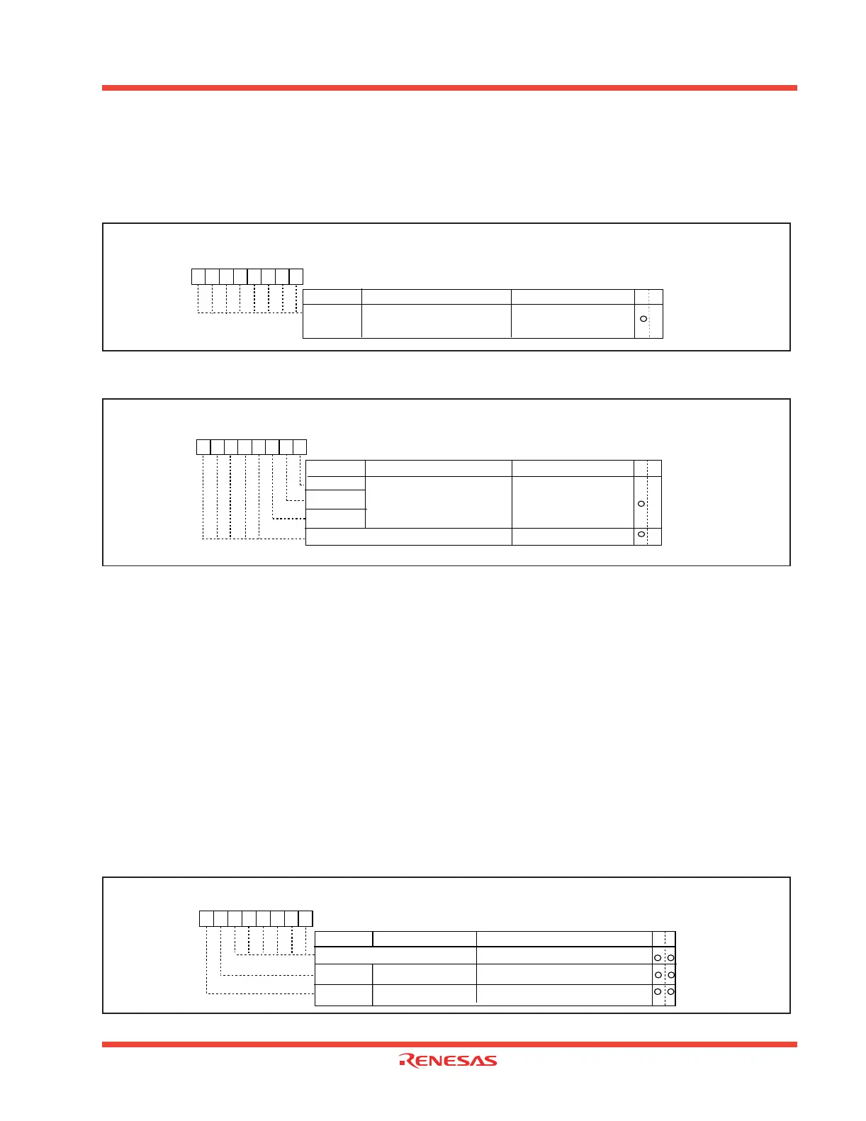
The USB Frame Number Low Register, shown in Figure 1.38, contains the lower 8 bits of the 11-bit frame
number received from the host. The USB Frame Number High Register, shown in Figure 1.39 contains the
upper 3 bits of the 11-bit frame number received from the host.
Figure 1.38: USB Frame Number Low Register
Figure 1.39: USB Frame Number High Register
1.2.18.4.8 USB ISO Control Register
The USB ISO Control Register, shown in Figure 1.40, contains two global bits, ISO_UPD and AUTO_FL for
controlling endpoints 1-4 isochronous data transfer.
When ISO_UPD = “0”, a data packet in an endpoint’s IN FIFO is always ‘ready to transmit’ upon receiving the
next IN_TOKEN from the host (with matched address and endpoint number) if the endpoint’s IN_PKT_RDY
is set.
When ISO_UPD = “1” and the ISO/TOGGLE_INIT bit of the corresponding endpoint’s IN CSR is set, the in-
ternal ‘ready to transmit’ signal to the transmit control logic is not activated when the endpoint’s IN_PKT_RDY
is set. Instead, it is activated when the next SOF is received, this way, the data loaded in frame n is transmitted
out in frame n+1. The ISO_UPD bit is a global bit for endpoints 1-4 and works with isochronous pipes only.
When AUTO_FL = “1”, ISO_UPD = “1”, a particular IN endpoint’s ISO/TOGGLE_INIT bit is set, and the IN
endpoint’s IN_PKT_RDY = “1”, the USB FCU detects a SOF packet and the USB FCU automatically flushes
the oldest packet from the IN FIFO. In this case, IN_PKT_RDY = “1”, indicates that two data packets are in
the IN FIFO. Because double buffering is a requirement for ISO transfer, MAXP must be set to less than or
equal to 1/2 of the FIFO size.
Figure 1.40: USB ISO Control Register
USB Frame Number Low Register
Symbol Address When reset
USBSOFL 0306
16
00
16
Bit nameBit symbol
b7 b6 b5 b4 b3 b2 b1 b0
FN0 to FN7
Function WR
Lower 8 bits of the 11-bit
frame number issued with a
SOF token
X
USB Frame Number High Register
Symbol Address When reset
USBSOFH 0307
16
00
16
Bit nameBit symbol
b7 b6 b5 b4 b3 b2 b1 b0
FN8
FN9
FN10
Function WR
Upper 3 bits of the 11-bit
frame number issued with a
SOF token
Reserved
Must always be set to "0"
X
X
0
0
0
0
0
USB ISO Control Register
Symbol Address When reset
USBISOC 0308
16
00
16
Bit name
Bit symbol
b7 b6 b5 b4 b3 b2 b1 b0
Function WR
Reserved
Must always be set to "0"
AUTO_FL
ISO_UPD
AUTO_FLUSH Bit
ISO_UPDATE Bit
0 : Hardware auto FIFO flush diabled
1 : Hardware auto FIFO flush enabled
0 : ISO_UPDATE disabled
1 : ISO_UPDATE enabled
0
0
0
0
0
0
 Loading...


