Universal Serial Bus
M30240 Group
Rev.1.00 Sep 24, 2003 Page 51 of 360
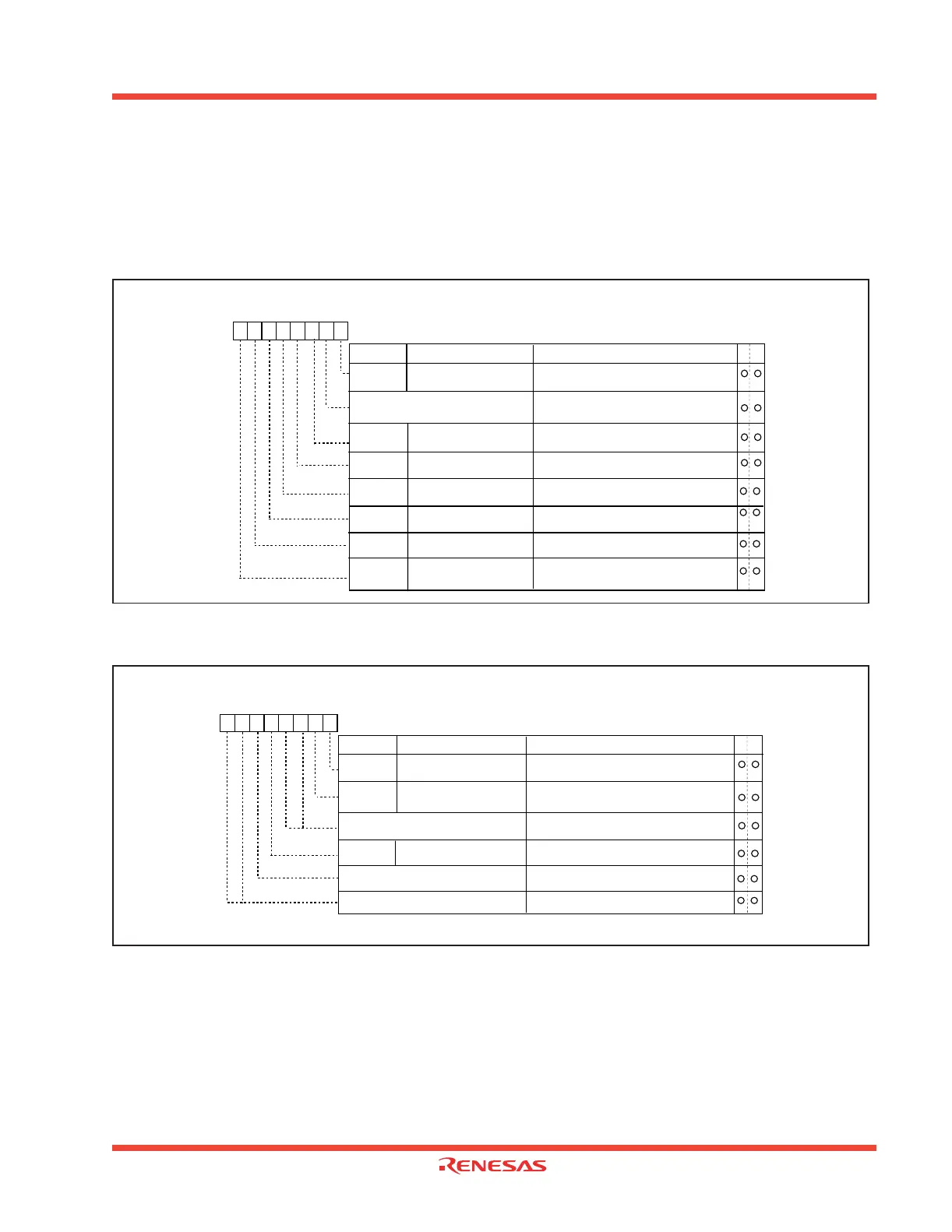
1.2.18.4.6 USB Interrupt Enable Registers 1 and 2
The USB Interrupt Enable Registers 1 and 2, shown in Figure 1.36 and Figure 1.37, are used to enable the
corresponding interrupt status conditions that can generate a USB Function Interrupt. When the bit to a cor-
responding interrupt condition is “0”, that condition does not generate a USB function interrupt. When the bit
is a “1”, that condition can generate a USB function interrupt. At reset, all USB function interrupt status condi-
tions are enabled.
Figure 1.36: USB Interrupt Enable Register 1
Figure 1.37: USB Interrupt Enable Register 2
USB Interrupt Enable Register 1
Symbol Address When reset
USBIE1 0304
16
FF
16
Bit nameBit symbol
b7 b6 b5 b4 b3 b2 b1 b0
Function
W
R
Reserved
Must always be set to "1"
INTEN0
INTEN2
INTEN3
INTEN4
INTEN5
INTEN6
INTEN7
USB Endpoint 0 Interrupt
Enable Bit
USB Endpoint 1 IN
Interrupt Enable Bit
USB Endpoint 1 OUT
Interrupt Enable Bit
USB Endpoint 2 IN
Interrupt Enable Bit
USB Endpoint 2 OUT
Interrupt Enable Bit
USB Endpoint 3 IN
Interrupt Enable Bit
USB Endpoint 3 OUT
Interrupt Enable Bit
0 : Interrupt disabled
1 : Interrupt enabled
0 : Interrupt disabled
1 : Interrupt enabled
0 : Interrupt disabled
1 : Interrupt enabled
0 : Interrupt disabled
1 : Interrupt enabled
0 : Interrupt disabled
1 : Interrupt enabled
0 : Interrupt disabled
1 : Interrupt enabled
0 : Interrupt disabled
1 :
Interrupt enabled
1
USB Interrupt Enable Register 2
Symbol Address When reset
USBIE2 0305
16 3316
Bit nameBit symbol
b7 b6 b5 b4 b3 b2 b1 b0
Function
W
R
Reserved
Must always be set to "0"
INTEN8
INTEN9
USB Endpoint 4 IN
Interrupt Enable Bit
USB Endpoint 4 OUT
Interrupt Enable Bit
USB Overrun/Underrun
Interrupt Enable Bit
0 : Interrupt disabled
1 : Interrupt enabled
INTEN12
0 : Interrupt disabled
1 : Interrupt enabled
0 : Interrupt disabled
1 : Interrupt enabled
Reserved
Must always be set to "1"
Reserved
Must always be set to "0"
0
0
1
0
0
 Loading...


