Transport Belt Charge Adjustments
J007/J010/J011 4-32 SM
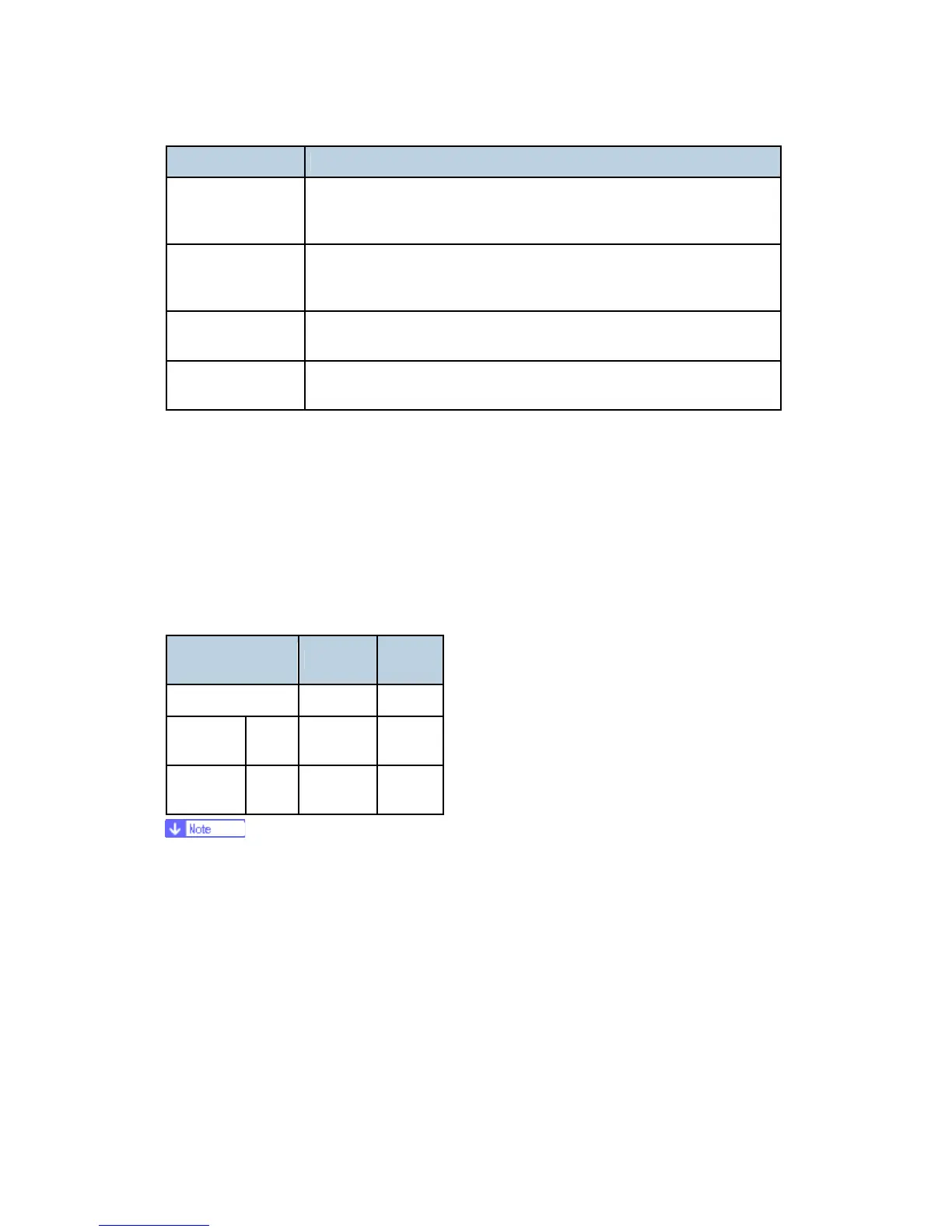
Ter m What It Means
TE Charge Area Trailing Edge Charge Area. This is the length of the area where
charge is applied to the Transport Belt below the trailing edge of the
paper above.
MID Charge Area Middle Charge Area. This is the length of the area were charge is
applied to the Transport Belt below the middle of the paper above
between the leading edge and trailing edge area.
LE/TE Charge
Pitch
The pitch of the charge (cycles) applied to both the leading edge
area and the trailing edge area.
MID Charge Pitch The pitch of the charge (cycles) applied to the middle area between
the leading edge and the trailing edge.
4.6.1 THE CHARGE AREA
The size of the charge area varies with what paper or special print medium is fed on the
transport belt.
The factory settings for the length of the areas where charge is applied at the leading and
trailing edges are shown below.
Table 2-1 Factory Settings for Charge Areas
Paper Type LE Area
TE
Area
OHP 35 mm 20 mm
Not OHP
Side
1
10 mm 20 mm
Side
2
35 mm 20 mm
"Side 1" denotes the side of the paper that prints during simplex or 1st side of
duplex printing.
"Side 2" denotes the side of the 2nd side of the paper that prints during duplex
printing.
"Not OHP" denotes specifically normal PPC, High-Gloss Paper, Glossy Paper,
Postcards, Envelopes, and OHP.
The settings for each charge area can be adjusted with SP1232 to SP1237 on the "2.
Engine Mainte." menu in the Service Mode. The settings are stored in NVRAM on the
main control board after they adjusted and remain in effect after the machine is cycled
off/on.
 Loading...