Rockwell Automation Publication 2713P-UM001G-EN-P - May 2022 23
Chapter 2
Mounting Considerations
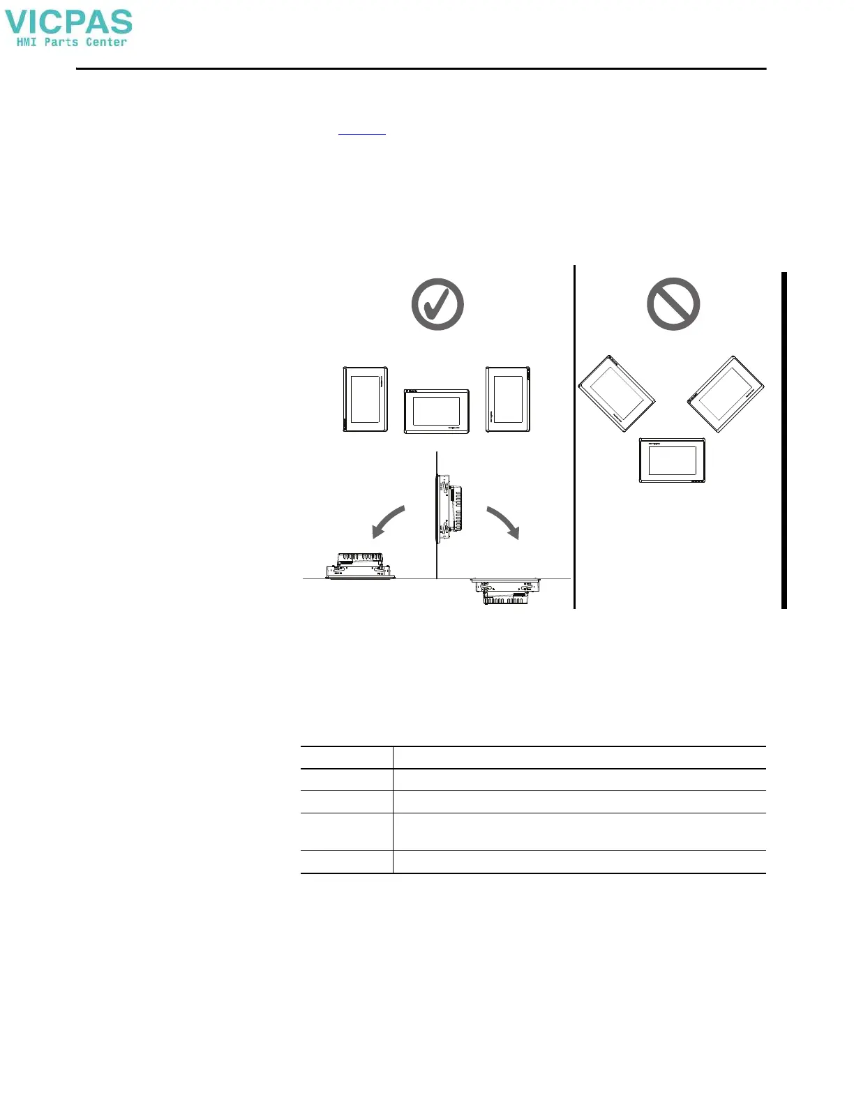
Consider the following items when mounting the PanelView 5310 terminal:
• Figure 2
shows the acceptable mounting positions where the terminal
functions properly.
• Mount the terminal at a height suitable for most operators.
• Mount the terminal in an area that has good lighting.
• Do not mount the terminal where it is exposed to direct sunlight.
Figure 2 - Acceptable and Unacceptable Mounting Positions
Mounting Clearances
Plan for adequate space around the terminal, inside the enclosure, for ventilation
and cables. Consider the heat from other devices in the enclosure. The ambient
temperature around the terminal must be 0…50 °C (32…122 °F).
Yes
≤ 90°
From Vertical
≤ 90°
From Vertical
No
Table 8 - Minimum Required Clearances
Terminal Area Minimum Clearance
Top 51 mm (2 in.)
Bottom 102 mm (4 in.)
Side 25 mm (1 in.)
102 mm (4 in.) is required to insert and remove an SD™ or SDHC™ card, or cable on one side
Back 0 mm (0 in.)

 Loading...


