8-8
Serial Communications
Remote I/O Examples (cont.)
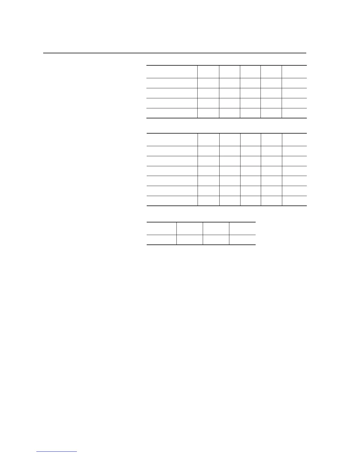
SMC Dialog Plus Controller Logic Control Addresses
①
SMC Dialog Plus Controller Status Addresses
①
SMC Dialog Plus Controller Feedback Address
①
①
The addresses shown are example-specific. Addresses for any given installation can be determined,
based upon the 1203-GD1 communication module switch settings for: rack address, starting group
number, block transfer, logic command/status, and reference/feedback by applying the I/O
addressing format for SLC-500 controllers.
②
The 1747-SN scanner resides in slot 1.
③
Based on the 1203-GD1 communication module switch settings (rack 2, starting group 0). Refer to
the 1747-SN User Manual, Publication 1747-6.6.
④
Refer to Table 8.A.
⑤
Refer to Table 8.B.
Bit Description I or O
Slot
②
Word
③
Bit
④
Address
Stop O 1 16 00 O:1.16/00
Start O 1 16 01 O:1.16/01
Option Command O 1 16 02 O:1.16/02
Clear Fault O 1 16 03 O:1.16/03
Bit Description I or O
Slot
②
Word
③
Bit
⑤
Address
Enabled I 1 16 00 I:1.16/00
Running I 1 16 01 I:1.16/01
Starting I 1 16 04 I:1.16/04
Stopping I 1 16 05 I:1.16/05
Fault I 1 16 07 I:1.16/07
At Speed I 1 16 08 I:1.16/08
I or O
Slot
②
Word
③
Address
I 1 17 I:1.17

 Loading...


