10-14
Troubleshooting
Power Module and Interface
Board Resistance Check (cont.)
2. Measure resistance between:
• pins J14 and J15 for phase L1/T1
• pins J9 and J10 for phase L2/T2
• pins J1 and J2 for phase L3/T3
The resistance should be approximately 100Ω.
If any of the resistances measure greater than 100Ω, recheck the
resistance values directly at the gate lead connectors as shown in
Figure 10.9.
Based on the results, one of the following actions will be required:
1. All resistance values are valid - Replace interface board.
2. Resistance(s) measure greater than 100Ω – Replace correspond-
ing power pole(s).
Thermistor Resistance
1. Measure resistance between:
• pins J6 and J24 for phase L1/T1
• pins J8 and J23 for phase L2/T2
• pins J7 and J22 for phase L3/T3
The resistance should be less than 500Ω.
If any of the resistances measure greater than 500Ω, recheck the
resistance values directly at the thermistor lead connectors as shown
in Figure 10.9.
Based on the results, one of the following actions will be required:
• If all resistance values are valid, replace interface board.
• If resistance(s) measure greater than 500Ω, replace the
corresponding power pole(s).
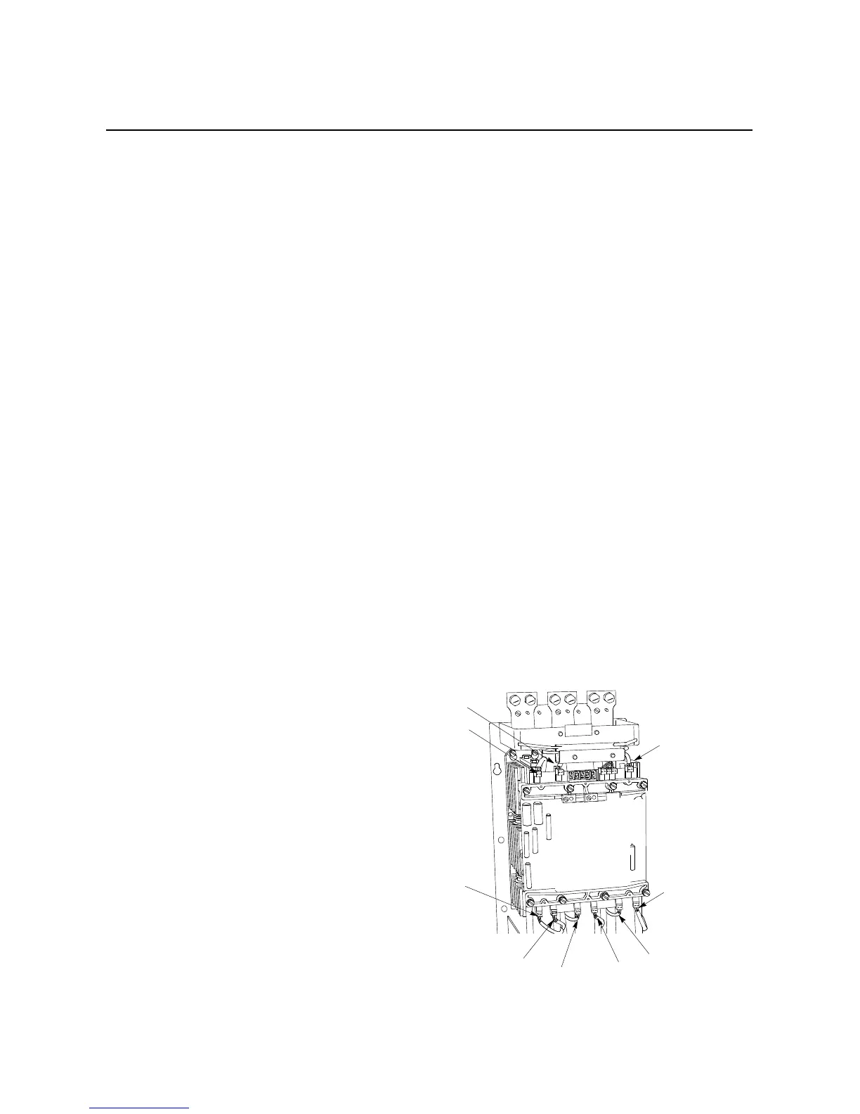
Figure 10.9 Gate and Thermistor Lead Identification (180–1000A)
Gate lead,
phase L2-T2
Gate lead,
phase L1-T1
Gate lead,
phase L3-T3
Gate lead,
phase L3-T3
Gate lead,
phase L2-T2
Gate lead,
phase L1-T1
Thermistor lead,
phase L1-T1
Thermistor lead,
phase L3-T3
Thermistor lead,
phase L2-T2

 Loading...


