Troubleshooting
10-13
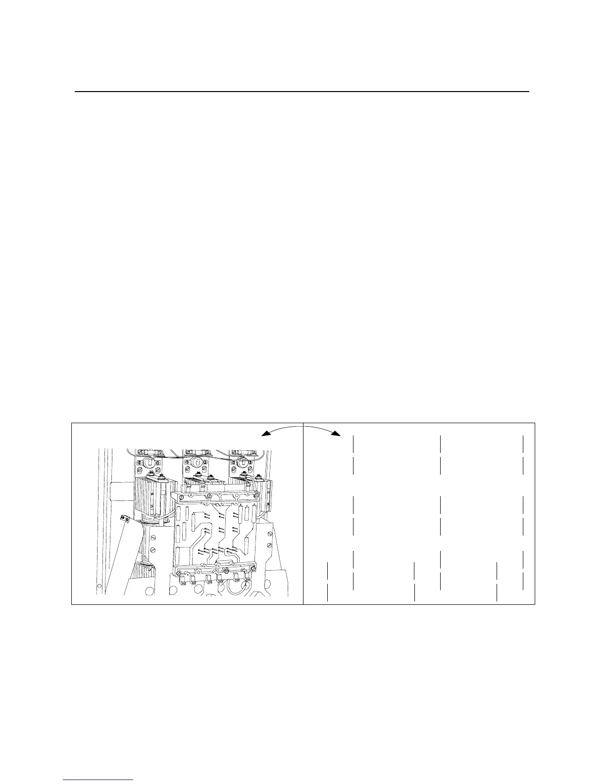
180-1000 Amp
Remove the control module per the instructions beginning on page
10-6. Refer to Figure 10.8 for interface board pin identification.
Shorted SCR Test
Using an ohmmeter, measure the resistance between the line and load
terminals of each phase on the controller. Resistance should be
greater than 10,000 ohms.
Feedback Resistance
1. Measure resistance between:
• pins J17 and J18 for phase L1/T1
• pins J12 and J13 for phase L2/T2
• pins J4 and J5 for phase L3/T3
Each resistance should be approximately 20KΩ.
2. Measure resistance between:
• pins J14 and J21 for phase L1/T1
• pins J9 and J20 for phase L2/T2
• pins J1 and J19 for phase L3/T3
Each resistance should be approximately 20KΩ.
If any of the measurements read “open,” replace the interface board.
Figure 10.8 Pin Locations for Power Pole Resistance Check (180–1000A)
Gate Lead Resistance
1. Measure resistance between:
• pins J16 and J18 for phase L1/T1
• pins J11 and J13 for phase L2/T2
• pins J3 and J5 for phase L3/T3
The resistance should be approximately 100Ω.
J18
J16
J14
J15
J17 J12 J4
J24 J23 J22
J21 J20 J19
J6 J8 J7
J3
J5 J13
J11
J2 J10
J1 J9

 Loading...


