page 120
July 01/2008
Effectivity: 914 Series
Edition 2 / Rev. 0
d04282
INSTALLATION MANUAL
BRP-Rotax
78
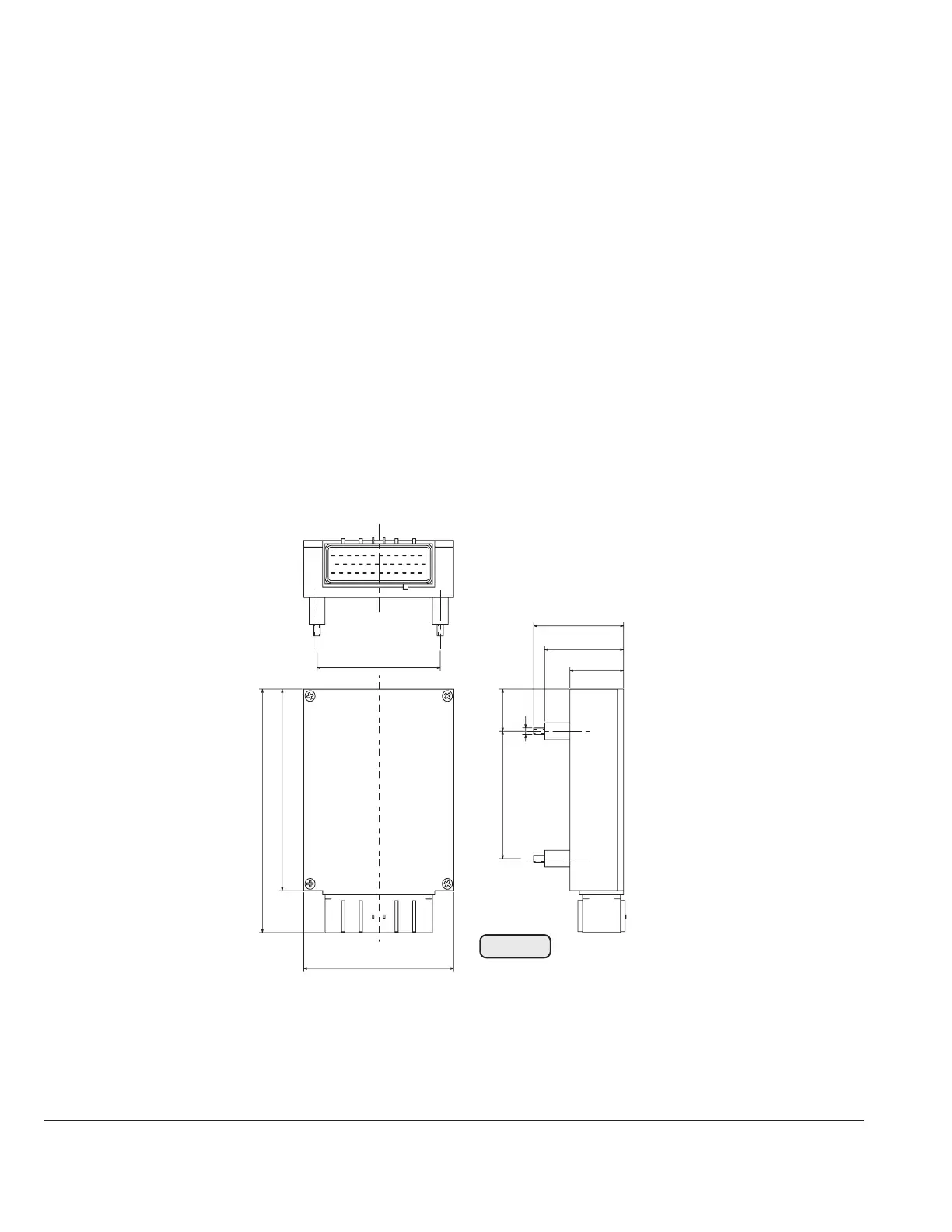
3,07 in.
57
2,24 in.
50
1,97 in.
34
1,34 in.
95
3,74 in.
145
5,7 in.
120
4,72 in.
76
2,99 in.
25
0,98 in.
M 4
Fig. 80
00092
▲ WARNING: Choose place of installation such, that operation is within the
specified temperature limits.
▲ WARNING: The TCU comprises electronic components and is therefore
completely sealed. The TCU is allowed to be opened only
by persons authorized by BRP-Rotax!
- connections:+ terminal: flexible cable 0,75 mm
2
(18 AWG)
white No. 1*
-
terminal:flexible cable 0,75 mm
2
(18 AWG)
white No. 25*
* from the 36 pole plug receptacle of the TCU with ring terminal 4,2 mm dia.
to DIN 46225
- fuse:
The TCU has to be protected by a slow blowing 2A fuse in accordance with
the wiring diagram, Fig. 69.

 Loading...


