ROXELL - 031 - 0516
FLEX-AUGER - INSTALLATION INSTRUCTIONS
III-57
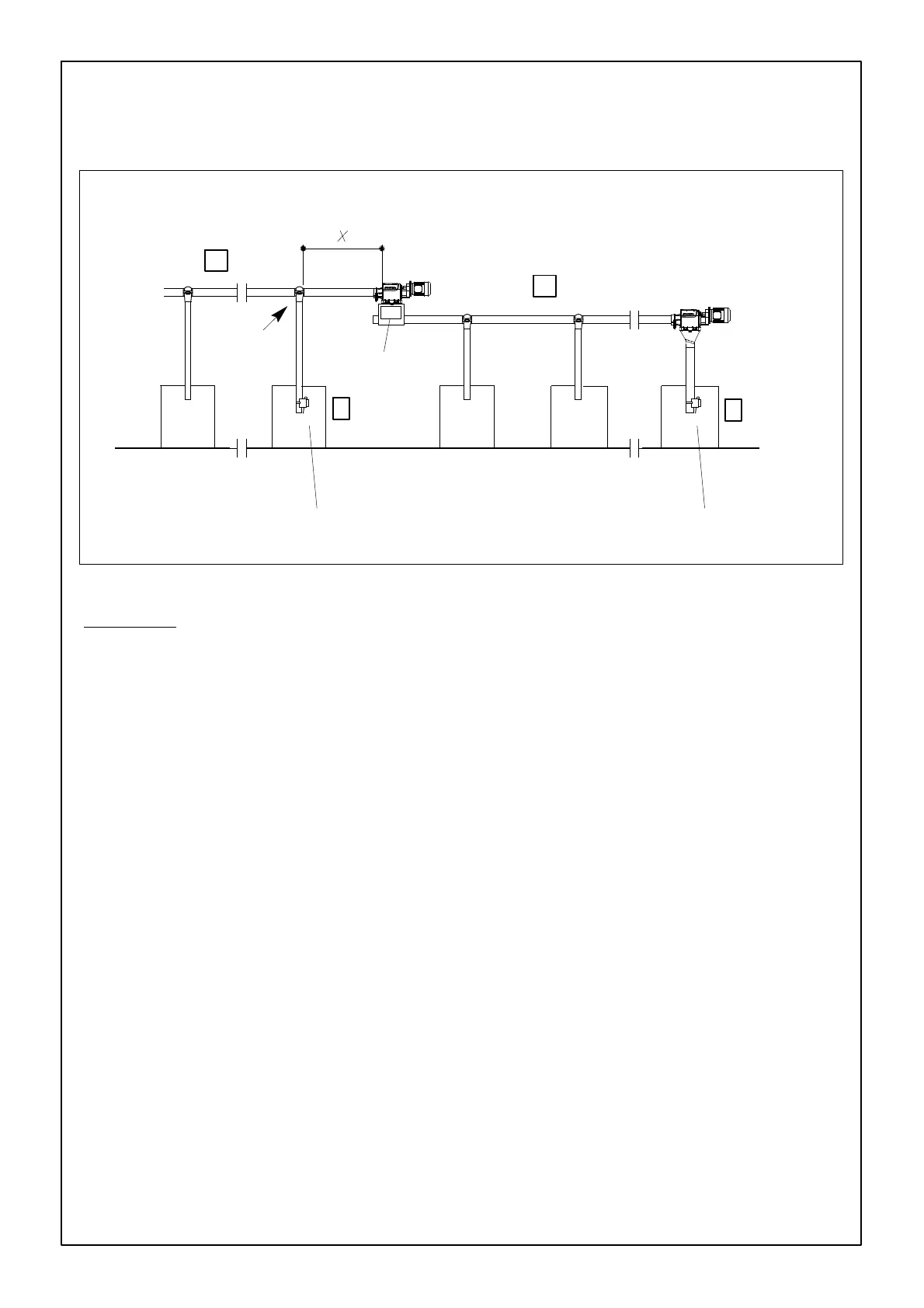
FIGURE 125.
FA
1
FA
2
1
2
Extension boot
100 % feed
drop
Time delay in minimum position. Time delay in maximum position.
PROVIDE 100 % FEED DROP FROM THE OUTLET JUST BEFORE THE EXTENSION BOOT
NO NC
1
2
TO INSTALL THE DROP TUBE LEVEL SWITCH IN A LINE WITH
EXTENSION BOOT
PRINCIPLE :
Flex-Auger 1 starts and runs until level switch 2 (NC) is activated.
Flex-Auger 2 always starts as FA 1 runs, but only during a preset period ”T”. This period is programmed on a
time relay in the control panel. Purpose : empty part ”x” at every start.
Example : X = 1m)--- T = A about 5 seconds
X = 2m) --- T = B about 10 seconds
Flex-Auger 2 always starts when level switch 1 (NO) is activated.