ROXELL - 031 - 0516
FLEX-AUGER - INSTALLATION INSTRUCTIONS
III-58
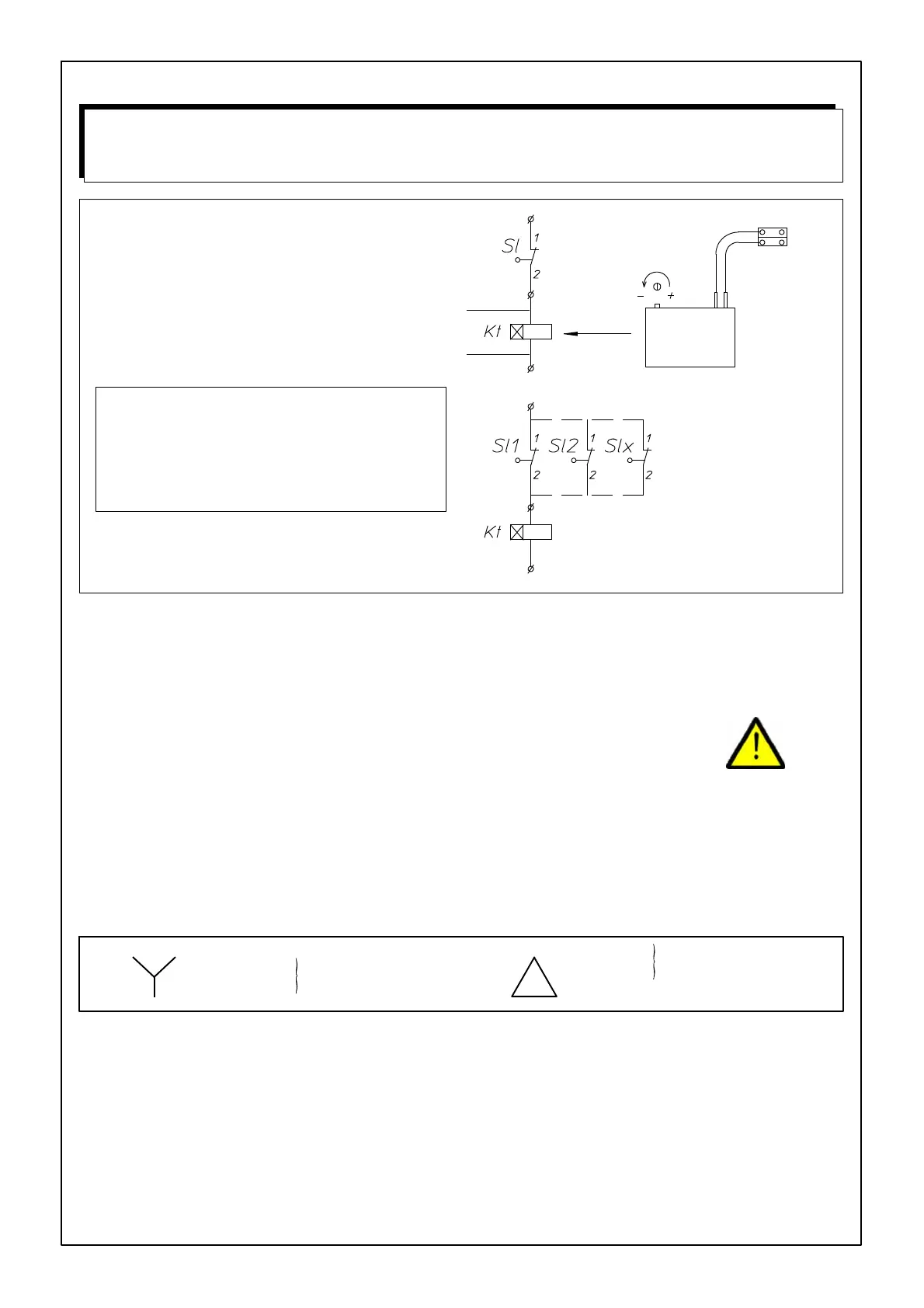
TO INSTALL THE DELAY BLOCK
Connect the delay block (delay ON) in series with the
level switch you want to activate.
FIGURE 126.
Red.
Adjusting button.
Adjustable from 1 to
100 seconds. (Ad-
justed on 100 sec-
onds when supplied)
One delay block will operate several
level switches in parallel.
You can connect to the level switch
box or to the control panel.
ALWAYS ADJUST TIME DELAY ON MAXI-
MUM
IF LEVEL SWITCH IS USED IN A FEEDING
TROUGH OR OUR 100KG HOPPER.
ALWAYS ADJUST TIME DELAY ON MINIMUM
IF LEVEL SWITCH IS USED AS INTERMEDI-
ATE SWITCH IN THE EXTENSION BOOT.
TIME DELAY
- STANDARD FOR 03100872 (DROP TUBE LEVEL SWITCH)
- OPTIONAL FOR 03100864 (HOPPER LEVEL SWITCH)
DANGER
ELECTRICITY .... WATCH OUT !
LEAVE CONNECTI ONS TO THE SYSTEM TO A QUALIFIED ELECTRICIAN !
- Wire the syst em with the utmost care and attention.
- Always provide a solid earthing.
- Check all connections before you switch on.
- Always f ollow the wiring diagrams included in the control panels.
- Compare setting of the motor protection with the data on the motor label.
- Motor protections are set at minimum by the manufacturer.
- If you do not use a Roxell control panel, make sure to provide the necessary motor protections.
- Compare motor label plate and motor connection with local voltage :
3x240V
3x200V
3x380V+N
3x415V+N
3x220V
(IEC38-3x400V+N)
(IEC38-3x230V)
MAXIMUM CABLE LENGTHS TO THE MOTORS: SEE PAGE III-77