ROXELL - 031 - 0516
FLEX-AUGER - INSTALLATION INSTRUCTIONS
III-63
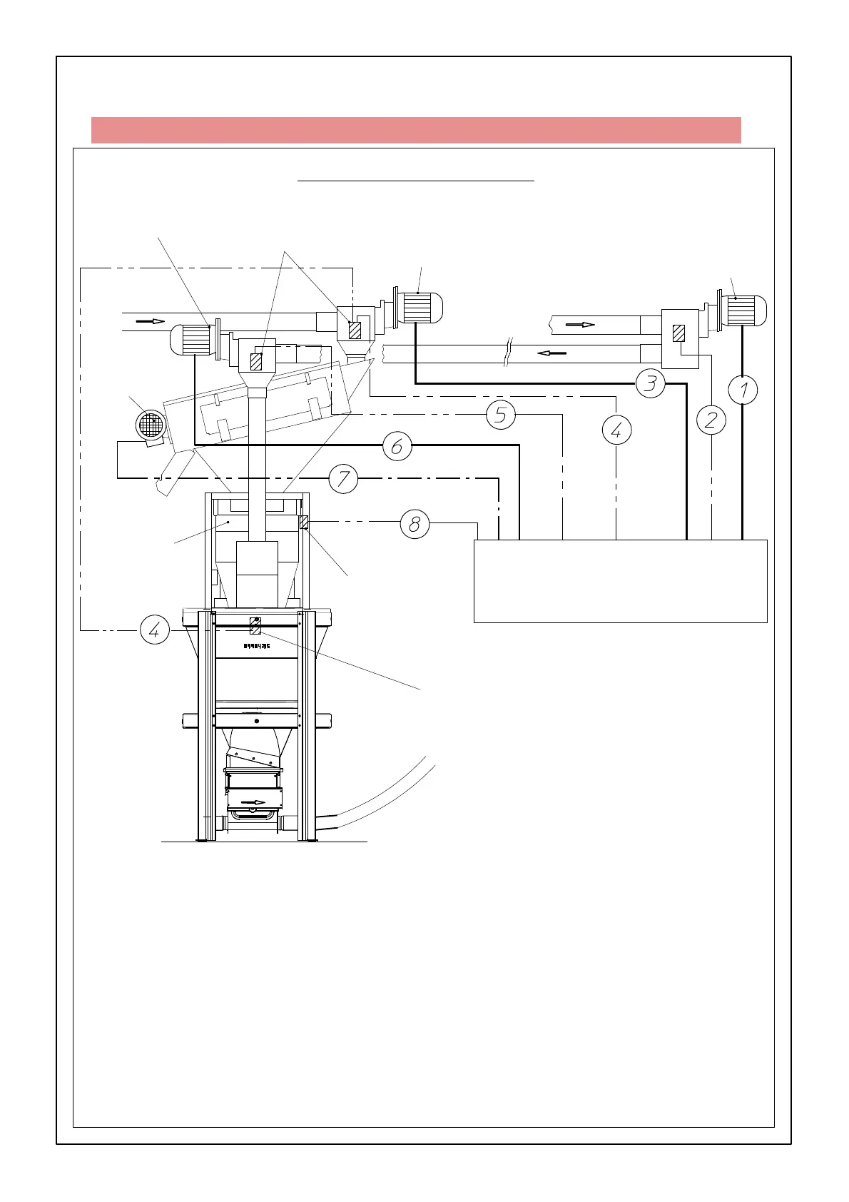
WIRING DIAGRAM CDS FEED SUPPLY SYSTEM
FIGURE 128.
Safety switch
Central control panel
FLEX-AUGER MODEL 75, 90 &
125
Max. switch
Impulse switch
: from FA3 motor (only for model 125) to CCP
: from FA3 safety switch to CCP
: from FA1 motor to CCP
: from max. switch weigher + FA1 safety switch to CCP
: from FA2 safety switch to CCP
: from FA2 motor to CCP
: from feed screen motor to CCP
: from i mpulse switch weigher to CCP
1=3x2.5+2.5
2=2x1.5
3=3x2.5
4=2x1.5
5=2x1.5
6=3x2.5+2.5
7=3x1.5+1.5
8=2x1.5+1.5
Weigher
Feed screen
FA2
FA1
FA3
FA = FLEX-AUGER
CCP = CENTRAL CONTROL PANEL
CABLE TYPES :
MAXIMUM CABLE LENGTHS TO THE MOTORS: SEE PAGE III-77