GB SGM Technology for lighting
User’s Manual 1.00 Pi
lot 3000
- 12 -
3 SYSTEM ARCHITECTURE
This chapter describes both Hardware and Software features of the Console.
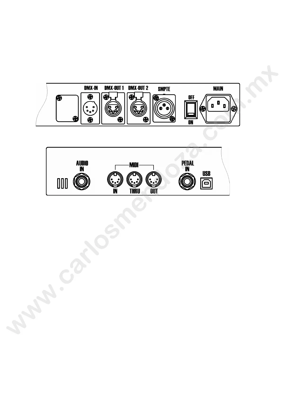
3.1 External connections
The first operations to be carried out during set-up are the external connections on the rear panel
of the Console. Connect the DMX lines to the output marked as DMX-OUT and DMX-OUT.
In addition, connect the SMPTE; MIDI or DMX-IN should those inputs be necess ry to be used with
the Pilot 3000.
Finally, connect the power cord and make sure t e g ound is the same used for the lighting
fixtures.
Turn ON the console by acting on the power sw ch positioned just beside the mains socket.
The Pilot 3000 will perform the boot procedure by loading the latest Software installed.
3.2 S
oftware interface
Pilot 3000 is equipped with a Col ur touch-screen panel having a resolution of 320X240 pixel (1/4
VGA) which is used as a display for the Software control system. By means of a touch is it possible
to carry out all the progra ming or playback editing procedure.
The console is also equ pped with a second display LCD capable of 40 characters on 2 lines which is
used to shows all the in o mation related to Playback Registers control.
MAIN INTERFACE
The Main Int rface of the Pilot 3000 is made of 3 different areas:
T ol b rs
Sel ction and Operating window
arameters window
et's examine the 3 areas and their use in the detail.