MX-3114N ADJUSTMENTS AND SETTINGS 5 – 9
3) Enter the adjustment value (specified value), and press [OK] key.
When [EXECUTE] key is pressed, the voltage entered in the procedure 3) is outputted for 30sec and the set value is saved.
When [EXECUTE] key is pressed again, the output is stopped.
By setting the default value (specified value), the specified output is provided.
ADJ 3 Image density sensor
adjustment
Before executing this adjustment, check to confirm the following
items.
* Check to confirm that the color image density sensor (image reg-
istration sensor F) and the black image density sensor (image
registration sensor R) are clean.
* Check to confirm that the image density sensor calibration plate
is clean.
* Check to confirm that the transfer belt is clean and free from
scratches.
3-A Image density sensor adjustment
The transfer belt surface are used to make the sensitivity adjust-
ment of the color image density sensor (image registration sensor
F) and the black image density sensor (image registration sensor
R).
This adjustment executes automatically at the outset of registration
adjustment operation and process control operation as well as
SIM44-2.
Normally, therefore, it is not required to perform this adjustment. It
is performed only when the sensor is replaced or when the adjust-
ment result is checked.
1) Enter SIM44-2 mode.
2) Press [EXECUTE] key.
The sensitivity adjustments of the color image density sensor
(image registration sensor F) and the black image density sen-
sor (image registration sensor R) are automatically performed.
After completion of the adjustment, the adjustment result is
displayed and [EXECUTE] key returns to the normal display.
If the adjustment is not completed normally, "ERROR" is dis-
played.
When an error occurs, check the following sections for any abnor-
mality.
• Color image density sensor (image registration sensor F)
• Black image density sensor (image registration sensor R)
•PCU PWB
• Transfer belt (dirt, scratch)
• Transfer belt cleaner
If any abnormality is found, repair and adjust again.
If an error occurs, the adjustment result is not revised.
ADJ 4 Image lead edge position,
image loss, void area, image
off-center, image magnification
ratio adjustment
(Automatic adjustment)
The following adjustment items can be executed automatically with
SIM50-28.
*ADJ 15
Print image position, image magnification ratio, void area, off-
center adjustment (Print engine) (Manual adjustment)
*ADJ 16
Scan image magnification ratio adjustment (Manual adjustment)
*ADJ 17
Scan image off-center adjustment (Manual adjustment)
*ADJ 18
Copy image position, image loss adjustment
(Manual adjustment)
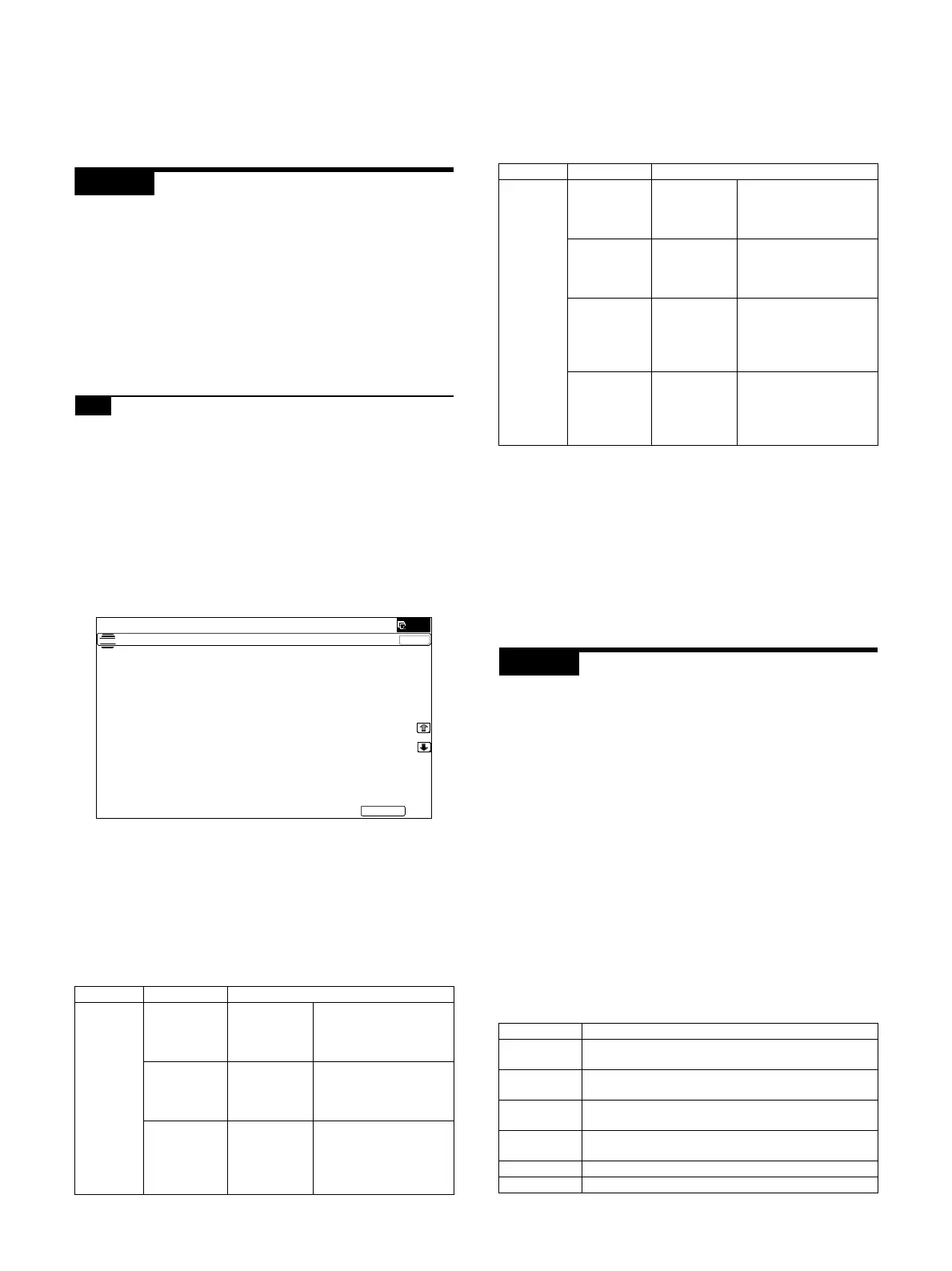
(Menu in SIM50-28 mode)
Mode Error display Error content
Adjustment
value for
process
control
operation
mode
BK_SEN_
ADJ_ERR
Black image
density sensor
adjustment
abnormality
PCS_K LED ADJ error
(The target value is not
obtained after retried
three times.)
CL_SEN_
ADJ_ERR
Color image
density sensor
adjustment
abnormality
PCS_CL LED ADJ error
(The target value is not
obtained after retried
three times.)
BELT_READ_
ERR
Transfer belt
surface
reading
abnormality
PCS_K GRND error (The
surface detection level is
maximum or the minimum
value difference is outside
a reference range.)
ǂǂǂ6,08/$7,21ǂǂ12
&/26(
7(67
352&21*$,1$'-8670(17
(;(&87(
3&6B&//('$'- 5(*B)*51'
3&6B./('$'- 5(*B5*51'
3&6B&/'$5. 5(*B)%(/70$;
3&6B.'$5. 5(*B)%(/70,1
3&6B.*51' 5(*B)%(/7',)
3&6B.%(/70$; 5(*B5%(/70$;
3&6B.%(/70,1 5(*B5%(/70,1
3&6B.%(/7',) 5(*B5%(/7',)
5(*B)/('$'- 5(*B)3$7&+.
5(*B5/('$'- 5(*B)3$7&+&
5(*B)'$5. 5(*B)3$7&+0
5(*B5'$5. 5(*B)3$7&+<
Adjustment
value for
image
registration
operation
mode
REG_SEN_
F_ADJ_ERR
Registration
sensor F
adjustment
abnormality
REG_F LED ADJ error
(The target value is not
obtained after retried
three times.)
REG_SEN_
R_ADJ_ERR
Registration
sensor R
adjustment
abnormality
REG_R LED ADJ error
(The target value is not
obtained after retried
three times.)
REG_BELT_
F_READ_
ERR
F side transfer
belt surface
reading
abnormality
REG_F GRND error (The
surface detection level is
maximum or the minimum
value difference is outside
a reference range.)
REG_BELT_
R_READ_
ERR
R side transfer
belt surface
reading
abnormality
REG_R GRND error (The
surface detection level is
maximum or the minimum
value difference is outside
a reference range.)
Display/Item Content
OC ADJ Image loss off-center sub scanning direction image
magnification ratio adjustment (Document table mode)
BK-MAG ADJ Main scanning direction image magnification ratio
adjustment
SPF ADJ Image loss off-center sub scanning direction image
magnification ratio adjustment (RSPF mode)
SETUP/
PRINT ADJ
Print lead edge adjustment, image off-center (each paper
feed tray, duplex mode) adjustment
RESULT Adjustment result display
DATA Display of data used when an adjustment is executed
Mode Error display Error content