Parameter Description
60Hz
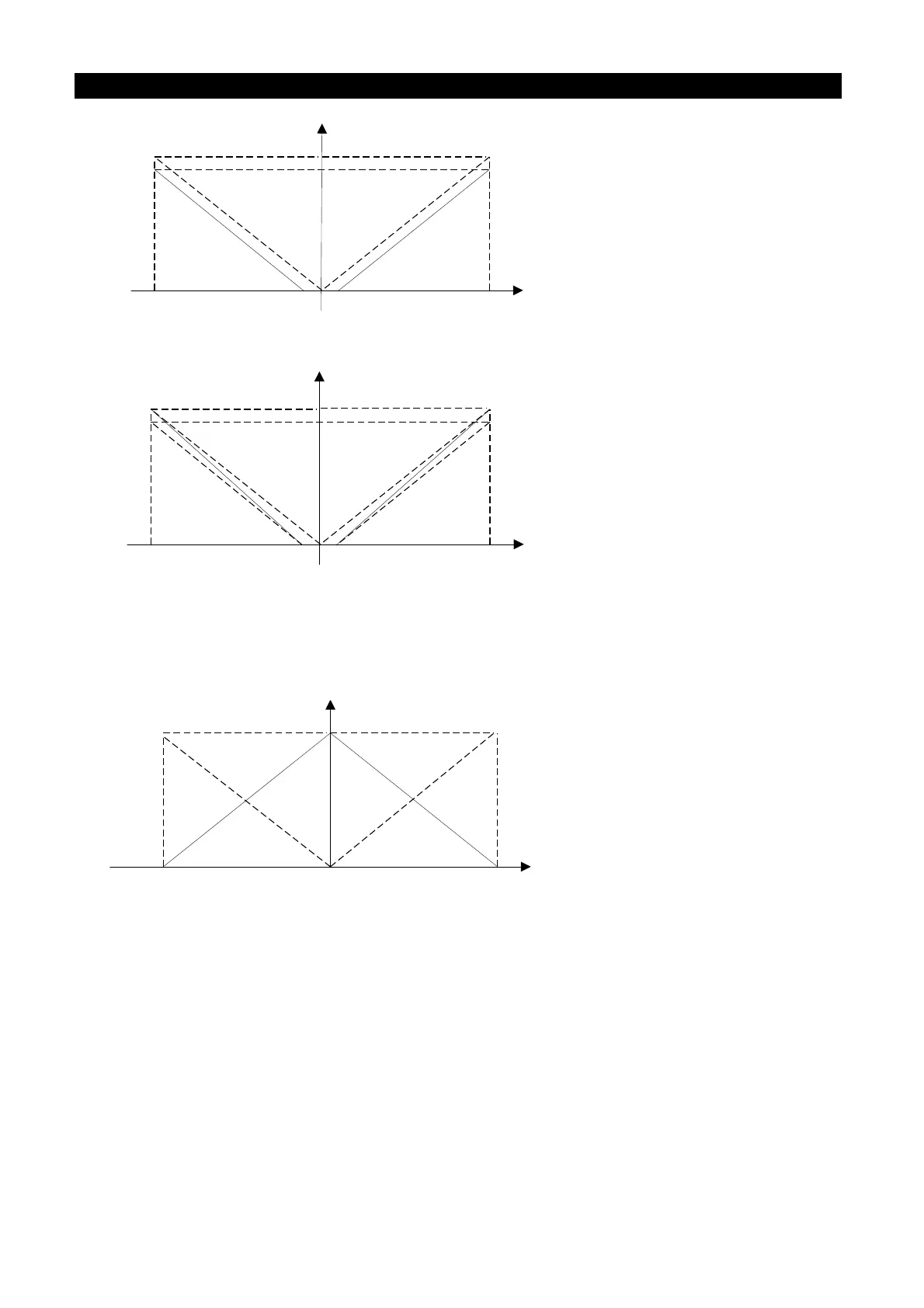
P.38=60Hz Max operation frequency
P.192=1V, P.193=10V The minimum/maximum input
positive voltage of terminal 2-5
P.194=0%, P.195=90% The setting corresponding to the
minimum/maximum positive voltage of terminal 2-5
P.510=0%, P.511=90% The setting corresponding to the
minimum/maximum negative voltage of terminal 2-5
P.512=1V, P.513=10V The minimum/maximum input
negative voltage of terminal 2-5
P.139 = 0% The bias rate of 2-5 voltage signal
P.195 = P.511 = 100.0 – (1V / 10V) * 100
10V
-10V
54Hz
1V-1V
Example 7: This example is an extension of Example 6. The wide application of this
example offers the users good flexibility.
60Hz
P.38=60Hz Max operation frequency
P.192=1V, P.193=10V The minimum/maximum input
positive voltage of terminal 2-5
P.194=0%, P.195=100% The setting corresponding to the
minimum/maximum positive voltage of terminal 2-5
P.510=0%, P.511=100% The setting corresponding to the
minimum/maximum negative voltage of terminal 2-5
P.512=1V, P.513=10V The minimum/maximum input
negative voltage of terminal 2-5
P.139 = 0% The bias rate of 2-5 voltage signal
10V
-10V
54Hz
1V-1V
Example 8: This example is an application of negative slop setup. The industry often uses
sensors for pressure, temperature or flow control. Some of the sensors output a 10V
signal at high voltage or high flow. This signal acts as a reference for the AC motor
drive to decelerate or to stop. The setup presented in Example 8 can satisfy this
type of application.
60Hz
P.38=60Hz Max operation frequency
P.192=0V, P.193=10V The minimum/maximum input
positive voltage of terminal 2-5
P.194=100%, P.195=0% The setting corresponding to the
minimum/maximum positive voltage of terminal 2-5
P.510=100%, P.511=0% The setting corresponding to the
minimum/maximum negative voltage of terminal 2-5
P.512=0V, P.513=10V The minimum/maximum input
negative voltage of terminal 2-5
P.139 = 0% The bias rate of 2-5 voltage signal
10V
-10V
0V
Example 9: This example integrates all the application of potentiometer. Together with the
application of forward and reverse rotation, it fits in the system easily for assorted
complicated application.

 Loading...

