Parameter Description
voltage
10V
60Hz
30Hz
0Hz
-10V
30Hz
60Hz
Reverse
rotation area
Forward
rotation area
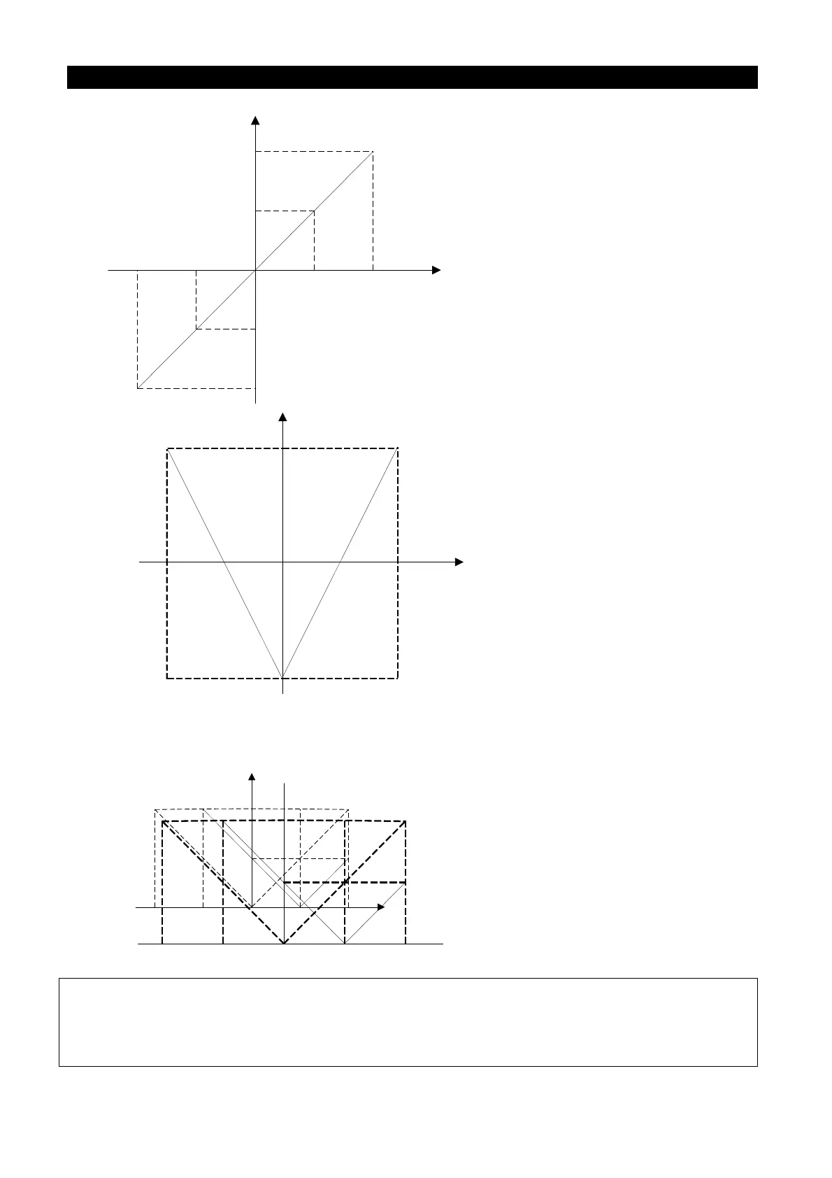
P.38=60Hz Max operation frequency
P.192=0V, P.193=10V The minimum/maximum input
positive voltage of terminal 2-5
P.194=0%, P.195=100% The setting corresponding to the
minimum/maximum positive voltage of terminal 2-5
P.510=0%, P.511=-100% The setting corresponding to the
minimum/maximum negative voltage of terminal 2-5
P.512=0V, P.513=10V The minimum/maximum input
negative voltage of terminal 2-5
P.139 = 0% The bias rate of 2-5 voltage signal
voltage
10V
60Hz
0Hz
60Hz
Reverse
rotation area
Forward
rotation area
5V
-10V -5V
P.38=60Hz Max operation frequency
P.192=0V, P.193=10V The minimum/maximum input
positive voltage of terminal 2-5
P.194=-100%, P.195=100% The setting corresponding to
the minimum/maximum positive voltage of terminal 2-5
P.510=-100%, P.511=100% The setting corresponding to
the minimum/maximum negative voltage of terminal 2-5
P.512=0V, P.513=10V The minimum/maximum input
negative voltage of terminal 2-5
P.139 = 0% The bias rate of 2-5 voltage signal
Example 10: This example is the application with bias voltage. The bias voltage is set by
P.139. When P.139=0%, there is no bias voltage; When P.139>0%, there is the
positive bias voltage; When P.139<0%, there is the negative voltage.
P.38=60Hz Max operation frequency
P.192=0V, P.193=10V The minimum/maximum input
positive voltage of terminal 2-5
P.194=0%, P.195=100% The setting corresponding to the
minimum/maximum positive voltage of terminal 2-5
P.510=0%, P.511=100% The setting corresponding to the
minimum/maximum negative voltage of terminal 2-5
P.512=0V, P.513=10V The minimum/maximum input
negative voltage of terminal 2-5
P.139 = 50% The bias rate of 2-5 voltage signal
60
60
Hz
Hz
10
10
V
V
-
-
10
10
V
V
5
5
V
V
-
-
5
5
V
V
0
0
30
30
Hz
Hz
Note: 1.The examples above are in the condition that P.500 is 1. It is also applicable when P.500 is other
nonzero value. Please refer to the definition instruction of P.500 for details.
2. The selection of range of voltage signal sampling across terminal 2-5 by parameter P.73 will affect
the parameters value of 2-5 terminal input signal in this part.

 Loading...

