Parameter Description
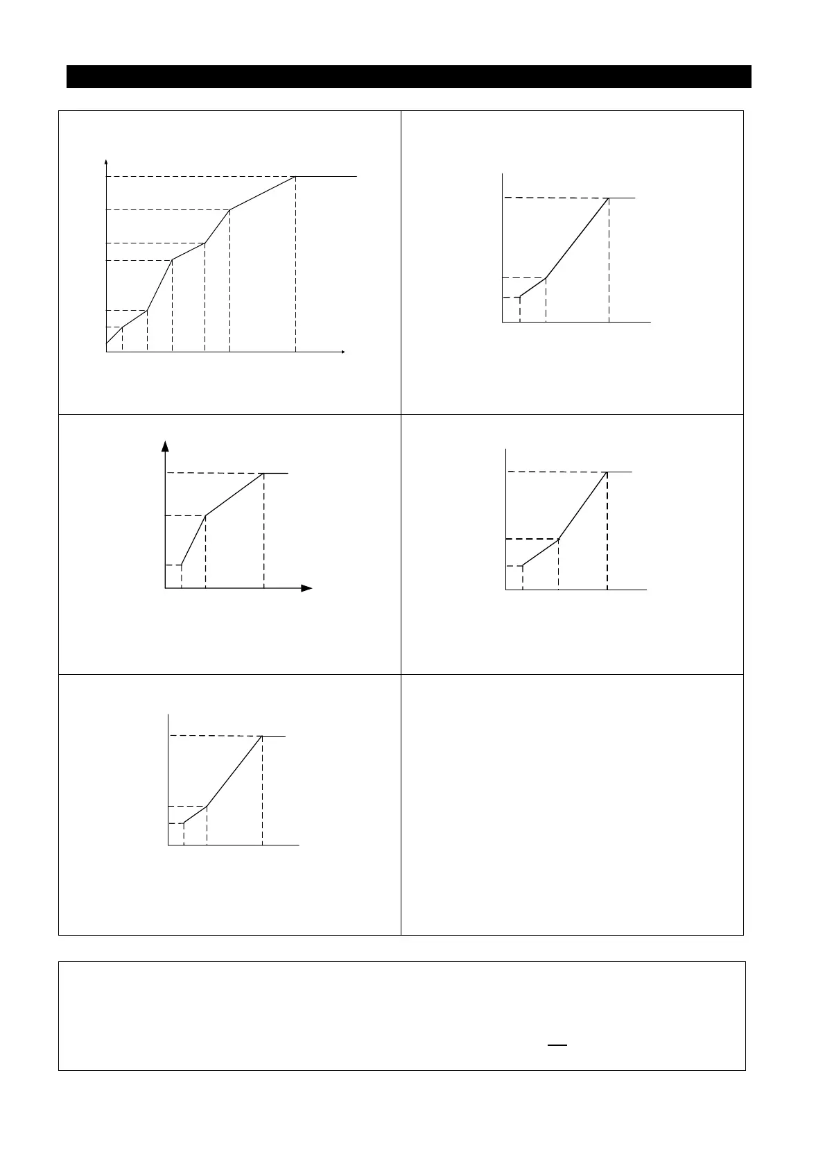
P.14=4
0
P.0
P.98 P.162 P.164 P.166
P.168
P.99
P.169
P.167
P.165
P.163
P.19
P.3
Output voltage
(%)
Output frequency (Hz)
Whether it is high startup torque or descending
torque, they are due to the set values (Note 1).
P.14=5
Output frequency
P.0
0 P.3
Output voltage
P.19
A
P.98=3.0
0.1
When P.14 = 5, the value of A is 7.1% (Note 2).
P.14=6,7,8
P.0
0 P.3
P.19
A
3.0
Output voltage
Output frequency
0.1
When P.
14=6, the value of A is 8.7%.
When P.14=7, the value
When P.14=8, the value of A is 12.0%.(Note 2)
P.14=9,10
P.0
0 P.3
P.19
A
30
0.1
Output frequency
Output voltage
When P.
14=9, the value of A is 20.0%.
When P.14=10, the value of A is 25.0%.(Note 2)
P.14=11,12,13
P.0
0 P.3
P.19
A
6
0.1
Output voltage
Output frequency
When P.14 = 11, the value of A is 9.3%. When P.14
= 12, the value of A is 12.7%. When P.14 = 13, the
value of A is 16.1%. (Note 2)
Note: 1. Referring to the diagrams above, set P.98 and P.99 if one point is needed. Set P.98, P.99, P.162
and P.163 if two points are needed. Set P.98, P.99, P.162, P.163, P.164 and P.165 if three points
are needed.
2. If you set P.14 between 5 and 13, the curve will be invalid when P. 0
is larger than the point A,
where point A equals to P.0.

 Loading...

