26 FLOWSIC100 Flare · Operating Instructions · 8013344/11L2/V 2-5/2018-10 · © SICK Engineering GmbH
Product Description
Subject to change without notice
2.1.2 System configuration
The following figures show cross-duct installations (FLOWSIC100 EX/ EX-RE, EX-S). In
principle,
the configuration is also valid for single side installations (FLOWSIC100 EX-PR).
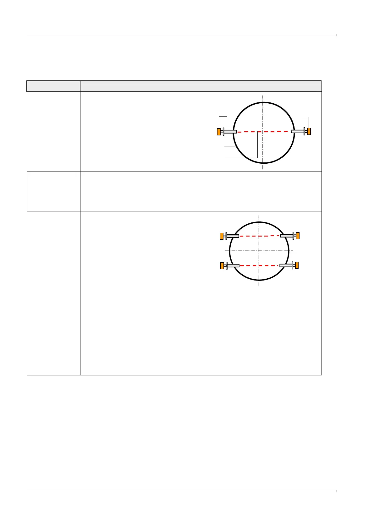
Configuration Description
1-path
measurement
2 sender/receiver units (1) are mounted on
the pipeline (2). The measurement path (3)
is positioned across the center of the
pipeline.
Special application conditions can require a
path positioning outside the center of the
pipeline (shortening of active measuring
path).
Instead of 2 sender/receiver units also a
probe version can be used (type EX-PR).
2x1-path
measurement
In this configuration the control unit MCUP serves two independent 1-path measurement
systems. Both pairs of sender/receiver units are connected to the same control unit MCUP.
Separate processing and output of the measuring results for both measuring points is
performed by the MCUP. Preferably both measurements are installed like standard 1-path
measurements in the center of the pipeline.
2-path
measurement
Two pairs of sender/receiver units are
installed at the same measuring location
and are connected to the same control unit
MCUP.
Both measurement paths should preferably
be positioned outside the center of the
pipeline and run parallel to one another.
Computation of both measuring paths to
one measuring result is performed via the
MCUP.
Two-path measurement is used to achieve higher measuring precision or for complicated
flow conditions.
Path compensation
The device is uses an integrated algorithm for path compensation in the case of a path
failure.
In trouble-free function, the system learns the relation of gas velocity and sound velocity
between both measurement paths. In case of a path failure, the system can calculate
theoretical values on basis of the learned path relations and can replace the invalid values
against them. In this way the path failure can be temporarily compensated and the
measurement is continued with slightly increased uncertainty. Under such conditions, the
measurement system automatically signals "Maintenance request".