Assembly and Installation
FLOWSIC100 Flare · Operating Instructions · 8013344/11L2/V 2-5/2018-10 · © SICK Engineering GmbH 127
Subject to change without notice
3.8.4 Connection of sender/receiver units
3.8.4.1 Terminal assignment in the terminal compartment of FLSE100-EXS/EXPR/EX/EXRE
sender/receiver units
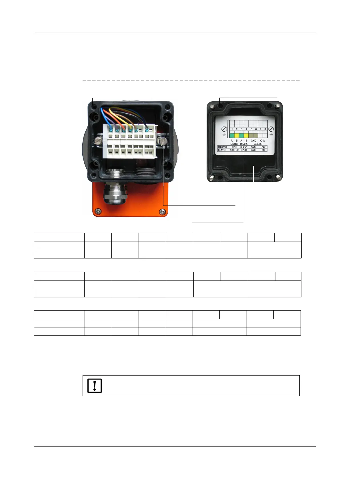
Fig. 60 Terminal compartment of FLSE100-EXS/EXPR/EX/EXRE sender/receiver unit for zone 2 or for zone 1
Connection of FLSE100-EX/EXRE Master
Connection of FLSE100-EX/EXRE Slave
Connection of FLSE100-EXS/EXPR
*: Cannot be changed
**: Applicable only for cables with wire color code according to DIN 47100
IF1: Communication between FLSE Master and MCUP (interface 1)
IF2: Communication between FLSE Master and FLSE Slave (interface 2)
Ground terminal
Connecting diagram
(on the inside)
Terminal compartment open Terminal compartment cover
Internal connection *
1 2 3 4 5 6 7 8
External connection ** Green Yellow Green Yellow Brown White
Assignment IF1 IF1 IF2 IF2 GND +24 V d.c.
Internal connection *
1 2 3 4 5 6 7 8
External connection Green Yellow Green Yellow Brown White
Assignment IF2 IF2 GND +24 V d.c.
Internal connection *
1 2 3 4 5 6 7 8
External connection ** Green Yellow Green Yellow Brown White
Assignment IF1 IF1 GND +24 V d.c.
NOTICE:
Self-locking terminals for wire sizes 0.5 .. 2.5 mm² (AWG20 ... AWG12).