Product Description
FLOWSIC100 Flare · Operating Instructions · 8013344/11L2/V 2-5/2018-10 · © SICK Engineering GmbH 31
Subject to change without notice
2.2 System components
2.2.1 FLSE100 sender/receiver unit
The sender/receiver units consist of the electronic unit (slave probe of type FLOWSIC100
EX-S without electronic unit), connecting piece and duct probe with transducer module.
The individual modules of the sender/receiver unit are firmly interconnected at the factory
to comply with the ex protection and thus form a unit which cannot be disassembled.
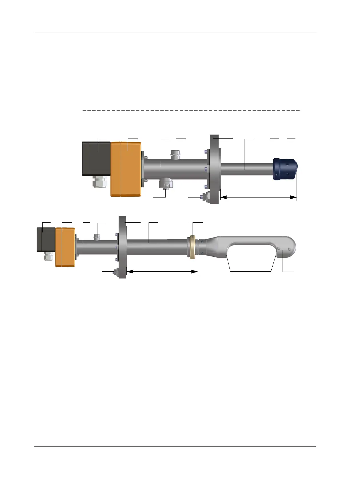
Fig. 5 Schematic diagram of the modules of the sender/receiver unit
1 2 3 4 5 6 7 8
9 10 Nominal length (NL)
1 Exe terminal compartment 7 Transducer
2 Electronic unit 8 Flow-optimized probe contour
3 Connection 9 Connection for slave probe (only for FLOWSIC100 EX-S)
4 Pressure balance element (not removable) 10 Ground terminal
5 Connection flange 11 Fixing ring
6 Duct probe 12 Supporting ring
Cross-duct version
Probe version
1 2 3 4 5 6 11 12
10 NL 78