136 FLOWSIC100 Flare · Operating Instructions · 8013344/11L2/V 2-5/2018-10 · © SICK Engineering GmbH
Assembly and Installation
Subject to change without notice
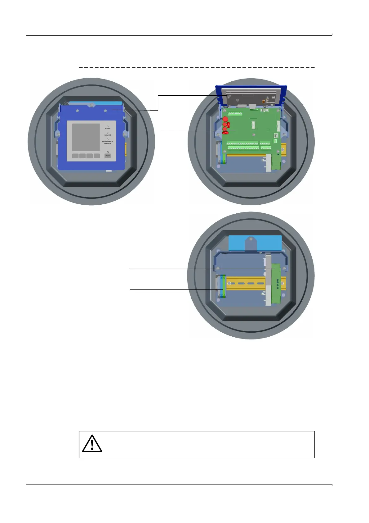
3.8.5.2 MCUP in explosion-protected version for Ex zone 1 and Cl I, Div 1
Fig. 66 MCUP component layout (with options) as explosion-protected version for zone 1 and Cl I, Div 1
3.8.6 Cabling
Work to be done
Connect connection cables according to Fig. 60 (
→
p. 127) and Fig. 61 (
→
p. 128) and
Fig. 67 (
→
p. 137) to Fig. 71 (
→
p. 141).
Connect cables for status signals (operation/malfunction, maintenance, check cycle,
maintenance requirement, limit value), analog output, analog and digital inputs accord
-
ing to requirements (
→
pg. 130, Fig. 63).
Connect power cable to terminals L1, N, PE (
→
pg. 129, Fig. 62)
Seal cable entries not in use with blind plugs
Optional I/O module
Connection diagrams
→
pg. 250, § 6.7
Inside view without
processor board
Option
Interface module
Processor
board
Display module
(collapsible)
WARNING:
Be sure to check the wiring before switching the supply voltage on.
Only modify wiring when disconnected from the mains and potential-free.