130 FLOWSIC100 Flare · Operating Instructions · 8013344/11L2/V 2-5/2018-10 · © SICK Engineering GmbH
Assembly and Installation
Subject to change without notice
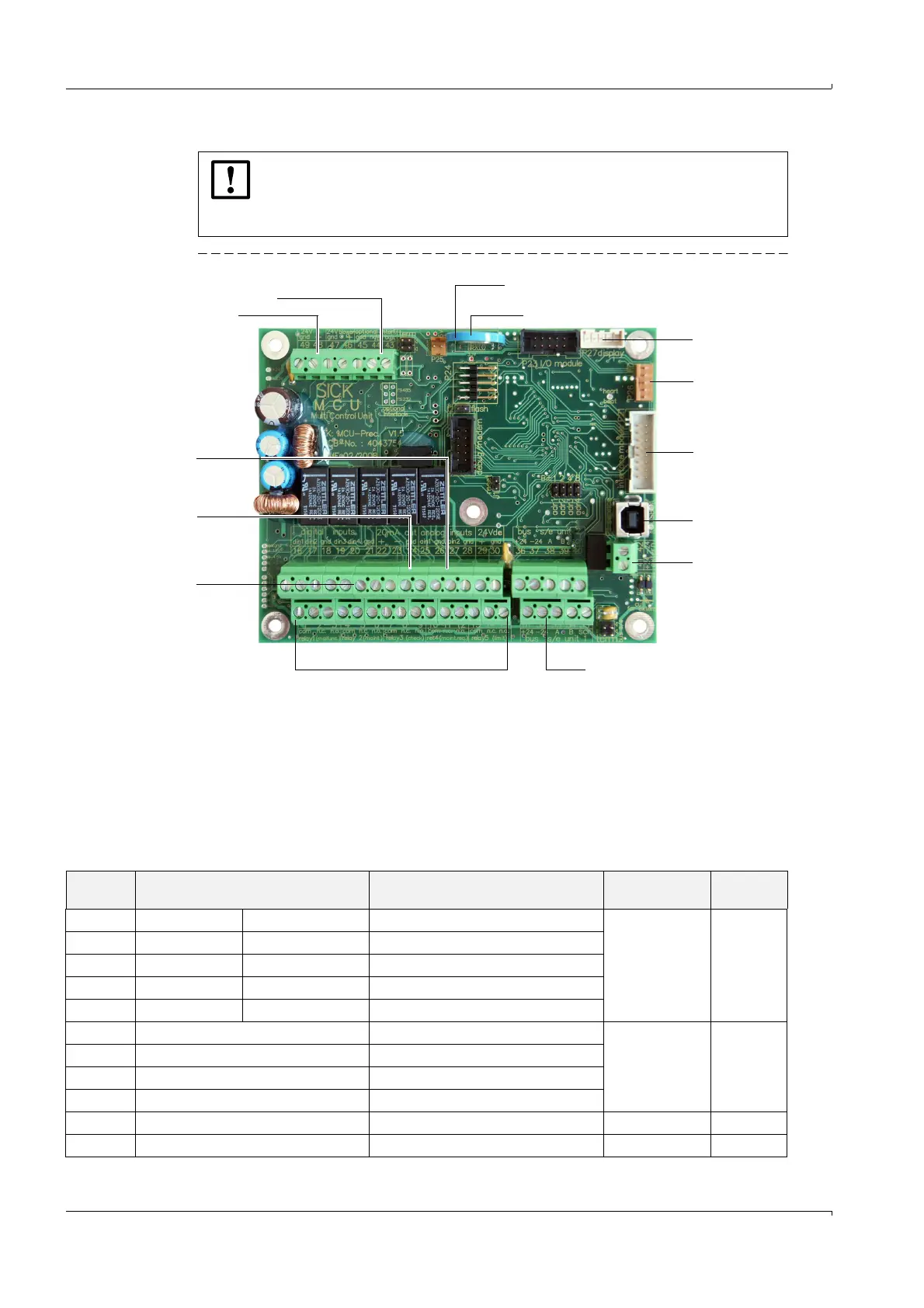
Fig. 63 MCUP processor board connections
Terminal data
NOTICE:
● Screw terminals for wire sizes 0.5 .. 1.5 mm² (AWG20 ... AWG16).
● All cables which are connected to the MCUP must be suitable for a mini-
mum working voltage of 300V.
1 RS232 (non-ex MCUP) or RS485 (ex MCUP) 8 Connection for optional I/O module
2 Supply voltage 24V d.c. 9 Backup battery type BR2032
3 Terminals for analog inputs1 and 2 10 Connection for optional display module
4 Terminals for analog output 11 Connection for LEDs
5 Terminals for digital inputs 1 to 4 12 Connection for optional interface module
6 Terminals for relays 1 to 5 13 USB plug
7 Terminals for sender/receiver unit master 14 Terminals 41, 42
14
13
12
11
10
9
8
6
5
4
3
2
1
7
Terminal Marking on the processor board Function Voltage rating
Ampere rat-
ing
1, 2, 3 com, n.c.
1)
, n.o.
2)
relay 1 (malfunc.) Indication of malfunction ≅ 30 V a.c./d.c.
1 A
4, 5, 6 com, n.c.
1)
, n.o.
2)
relay 2 (maint.) Indication of maintenance
7, 8, 9 com, n.c.
1)
, n.o.
2)
relay 3 (check.) Indication of function check
10, 11, 12 com, n.c.
1)
, n.o.
2)
relay 4 (maint.requ.) Indication of maintenance request
13, 14, 15 com, n.c.
1)
, n.o.
2)
relay 5 (limit) Indication of limit violation
16, 18 din1, gnd Digital input 1 (active low forced to gnd)
5.5 V d.c. max. 1 mA
17, 18 din2, gnd Digital input 2 (active low forced to gnd)
19, 21 din3, gnd Digital input 3 (active low forced to gnd)
20, 21 din4, gnd Digital input 4 (active low forced to gnd)
22, 23 +, - Analog output (20 mA) 20 ... 28 V d.c. max. 22 mA
24 gnd Ground