Assembly and Installation
FLOWSIC100 Flare · Operating Instructions · 8013344/11L2/V 2-5/2018-10 · © SICK Engineering GmbH 129
Subject to change without notice
3.8.5 MCUP connections
3.8.5.1 MCUP version without explosion protection and for use in zone 2 and Cl I, Div 2 / zone 2
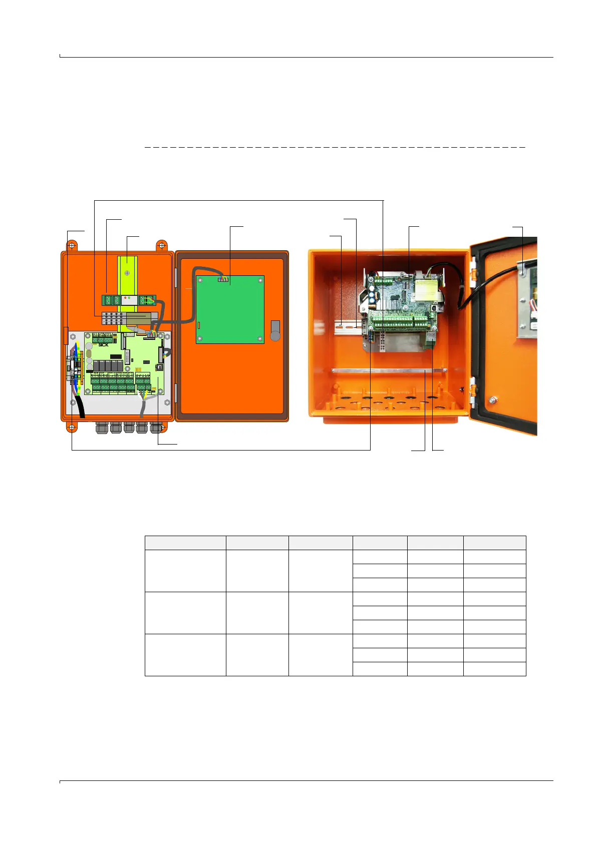
Version in wall housing
Fig. 62 MCUP component layout (with options)
Terminals for power supply, screw free 0,5 ...2,5 mm2 (AWG 20 up to AWG 12)
1)
: Wide range, not for Div 2 / zone 2 version
2)
: Automatic switching
3)
: It may only be used a power supply with safe mains isolation (PELV).The negative
terminal is grounded to the housing of device.
DISPLAYMODUL
relay 3 relay 4 relay 5
BUS - S /E unit 1
BUS
Term
Ter m
BUS - S/E unit 2
relay 1
relay 2
com nc. no.com nc. no.com nc. no. com nc. no.com nc. no.
Reset
MCUP compact size housing
1 Optional I/O modules 5 Fuse T2A
2 Optional interface module 6 Processor board
3 Hat rail 7 Terminals for power supply
MCUP medium size housing
8
7
6
5
4
3
2
1
3
5
6
4
2
Power supply version Voltage rating Wattage rating Terminal no. Marking Function
90 ... 250 V a.c.
1)
90...250 V a.c. max. 50 W 1 L1 Phase conductor
2 N Neutral wire
3 Earth symbol Earthing
115/230 V a.c.
2)
115/230 V a.c. max. 40 W 1 L1 Phase conductor
2 N Neutral wire
3 Earth symbol Earthing
24 V d.c.
3)
24 V d.c. max. 30 W 1 +24 V d.c. plus pole
2 GND minus pole
3 Earth symbol Earthing