Start-up and Parameter Settings
FLOWSIC100 Flare · Operating Instructions · 8013344/11L2/V 2-5/2018-10 · © SICK Engineering GmbH 167
Subject to change without notice
4.2.2 Entering application specific parameters for single-path configuration in the
MCUP
Select device file "MCU-P" and move it to the "Project " window.
Set the MCUP to "Maintenance" mode and enter the Level 1 password (
→
pg. 161,
§ 4.1.4).
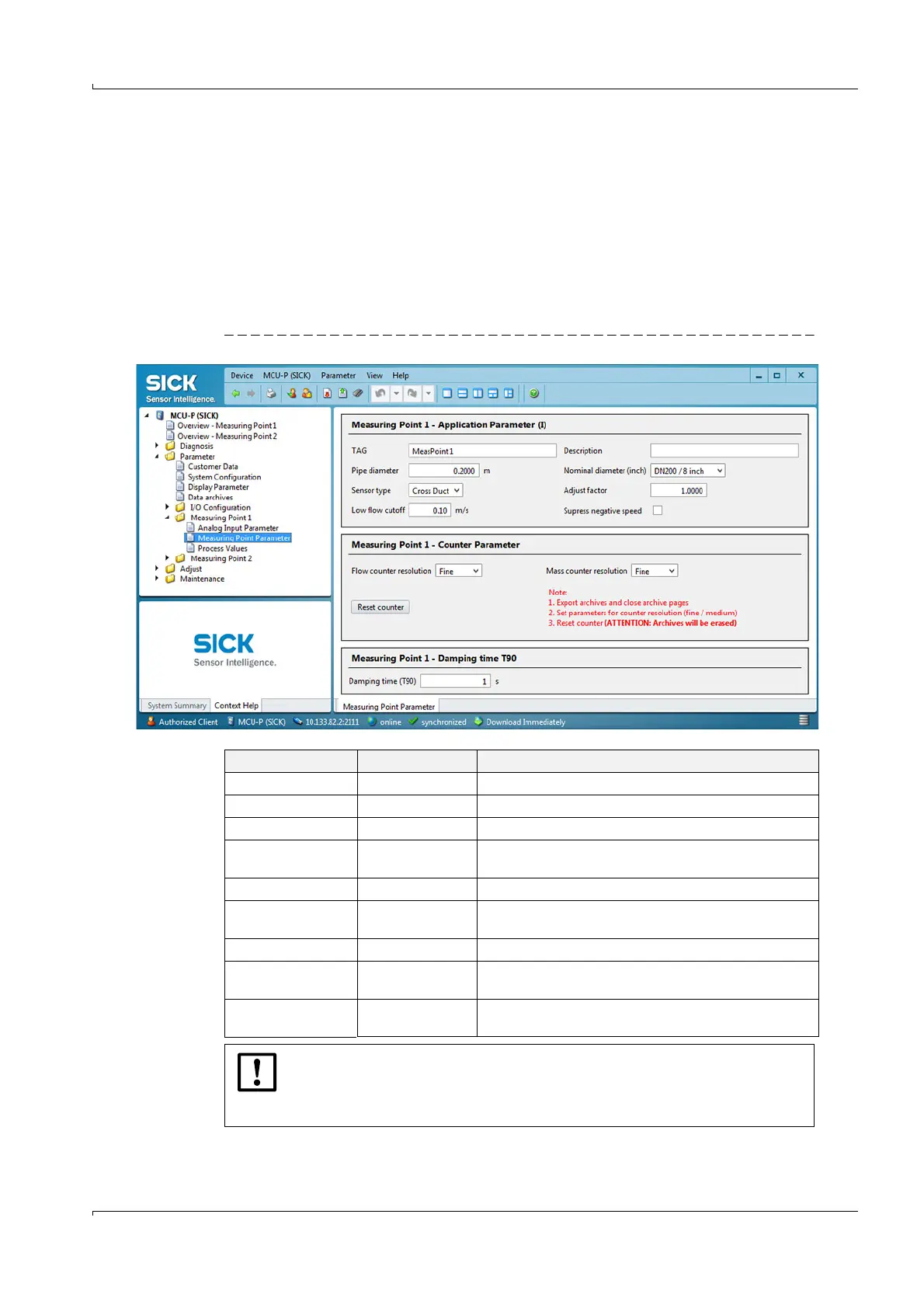
Select the "Parameter / Measuring Point 1(2/3) / Measuring Point Parameter" direc-
tory.
Enter the data in the "Measuring Point 1 - Application Parameter (I)" group as listed in
the following table.
Fig. 102 "Parameter / Measuring Point 1 / Measuring Point Parameter" directory
Entry field Parameter Remark
TAG Name TAG No. of the measuring point
Description Name Description of measuring point
Pipe diameter Value Pipe diameter in m
Nominal diameter
(inch)
Value Select the corresponding value
Sensor type Installation version Select the corresponding type (cross-duct or probe)
Adjust factor Value
Has to be determined by a comparision measurement;
without measurement enter "1"
Low flow cut-off Value Minimum velocity of gas to be suppressed
Suppress negative
speed
Active A negative gas velocity is suppressed
Damping time (T90) Value in s
Response time of measured value at selected measuring
point
NOTICE:
For flow calibrated devices the coefficients CC0 … CC4 must be the same as
those detailed on the calibration certificate. If necessary, set the parameters in
SOPAS ET with values from the calibration certificate.