86 FLOWSIC100 Flare · Operating Instructions · 8013344/11L2/V 2-5/2018-10 · © SICK Engineering GmbH
Assembly and Installation
Subject to change without notice
3.3.1 Fitting the nozzles on the pipeline (measuring systems without meter body)
The nozzles are manufactured precisely at the factory according to customer specifications
for fitting on the pipeline.
Notes for installations in existing pipelines (hot tapping)
● For calculation of the precise inner diameter of the pipeline the wall thickness have to
be determined very exactly. Schedule information alone is not sufficient.
● All exact geometric dimensions for fitting the nozzles in the pipeline (see following
instructions) have to be documented during nozzle installation. At commissioning of the
FLOWSIC100 Flare the geometric dimensions from the nozzle installation are needed
for correct parameterization of the device.
3.3.1.1 Determining the nozzle positions and marking on the pipeline
General preparation work
The installation tool (
→
pg. 58, § 2.2.3) contains a foil strip (length approx. 4 times the pipe
diameter, width approx. 0.75 of the pipe diameter) as a resource to determine the exact
position of the nozzle on the pipeline. The foil strip is prepared with nozzle markings for
different pipe diameters.
Fig. 35 General preparation work
NOTICE:
The exact positioning of the nozzles is prerequisite for low measuring
uncertainty.
Maximum tolerances for nozzle positions and fitting angle of the nozzles:
– Maximum tolerance ± 1 mm / ± 1 °
– Tolerance for best uncertainty results ± 0.1 mm / 0.1 °
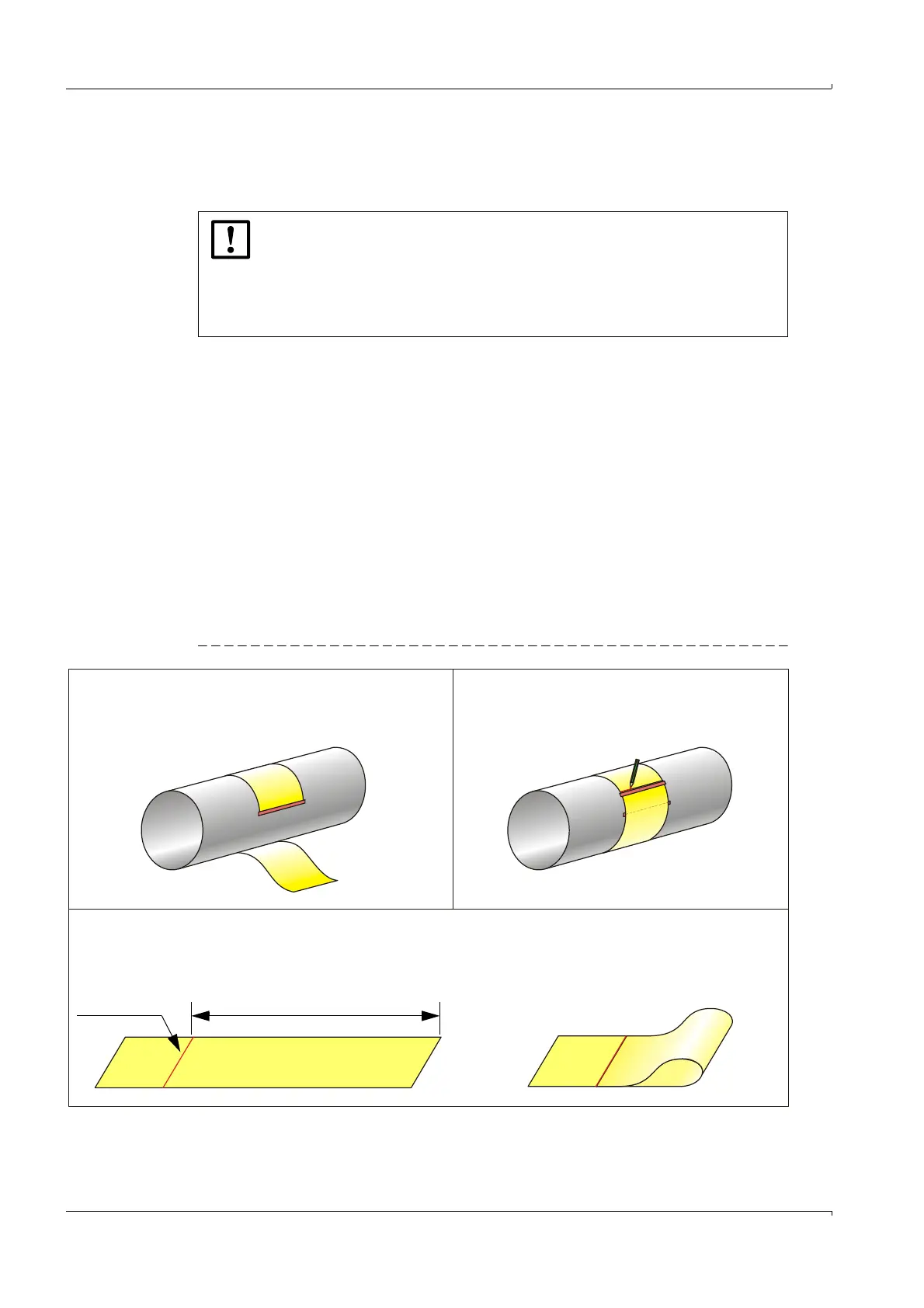
1) Wind the strip around the pipeline at the selected measur-
ing point (ensure exact right-angled alignment) and secure
(e.g. with adhesive strips).
2) Mark the strip where overlapping starts.
3) Loosen the fastening, take the strip off and lay it out on a level surface.
For 1 path measurements, fold the strip to the
overlap line so that the part matching pipe
circumference (U) is halved.
U
Overlap line