66 FLOWSIC100 Flare · Operating Instructions · 8013344/11L2/V 2-5/2018-10 · © SICK Engineering GmbH
Product Description
Subject to change without notice
2.2.5 Connection cables and cable glands
Connection cables serve communication between sender/receiver units FLSE100 and
between sender/receiver units and control unit MCUP. SICK offers standard cables and
cable glands:
a) Connection between sender/receiver units:
– cable UNITRONIC® Li2YCYv (TP) with reinforced black outer sheath, fixed cable
length
– cable glands metric M20, NPT ½", material brass and stainless steel
b) Connection between sender/receiver unit master and MCUP:
– cable UNITRONIC® Li2YCYv (TP) with reinforced black outer sheath, meter good with
free selectable lengths in steps of 5 m
– cable glands metric M20, M25, NPT ½", NPT ¾", material brass and stainless steel
Other connection cables for MCUP (power supply, outputs MCUP etc.) are not in the SICK
scope of delivery.
The maximum overall length of all cables of a measuring system (installation of 1 pair of
s/r units) is up to 1,000 m. For cabling of 2-path or 3x1 path systems (installation with 2
pairs and 3 pairs of s/r units) the maximum possible cable length is reduced according to
the number of pairs of s/r units (500 m for 2 pairs of s/r units, 300 m for 3 pairs of s/r
units).
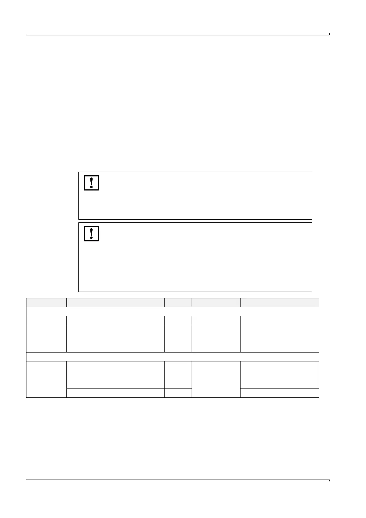
NOTICE: Factory pre-installed cable glands at S/R units and MCUP
Install only fixed cables and wires in the cable glands. The plant operator
must ensure an appropriate strain relief.
The cable and conduit entries must be installed with mechanically
protection against inadmissible impact energy according to EN 60079-0
section 26.4.2.
NOTICE: Suitability of factory pre-installed plastic cable glands at MCUP
ATEX Zone 2
In accordance with EN 60079-0, section 26.4.2 the pre-installed PA plastic
cable glands at MCUP ATEX zone 2 are suitable for equipment group II with
low degree of mechanical hazard (impact energy “low”, tested with drop
height 0.4m or 4J).
If there is a risk of higher mechanical stress, especially at low
temperatures, the use of metal cable glands is recommended (available on
request).
Cable type Connection Length Use for device type Remark
Cables for interconnection FLSE100 master - FLSE100 slave
Analog cable Exi TNC at both ends 3 m FLOWSIC100 EX-S for analog connection
UNITRONIC
Li2YCYv(TP),
2x2x0.5 mm²
twisted pair
single wires, tinned leads at both ends 5 m
10 m
FLOWSIC100 EX,
FLOWSIC100 EX-RE
Ex-d cable glands must be fitted
to cables for sender/receiver units
without an Exe terminal
compartment.
Cables for interconnection FLSE100 master - MCUP
UNITRONIC
Li2YCYv(TP),
2x2x0.5 mm²
twisted pair
single wires, tinned leads at both ends 5 m
10 m
FLOWSIC100 EX-S,
FLOWSIC100 EX,
FLOWSIC100 EX-RE,
FLOWSIC100 EXPR
Ex-d cable glands must be fitted
to cables for sender/receiver units
without an Exe terminal
compartment.
single wires at both ends yard good Maximum length 500 m