Product Description
FLOWSIC100 Flare · Operating Instructions · 8013344/11L2/V 2-5/2018-10 · © SICK Engineering GmbH 65
Subject to change without notice
*
): not applicable for CSA approved versions
**): no explosion protection
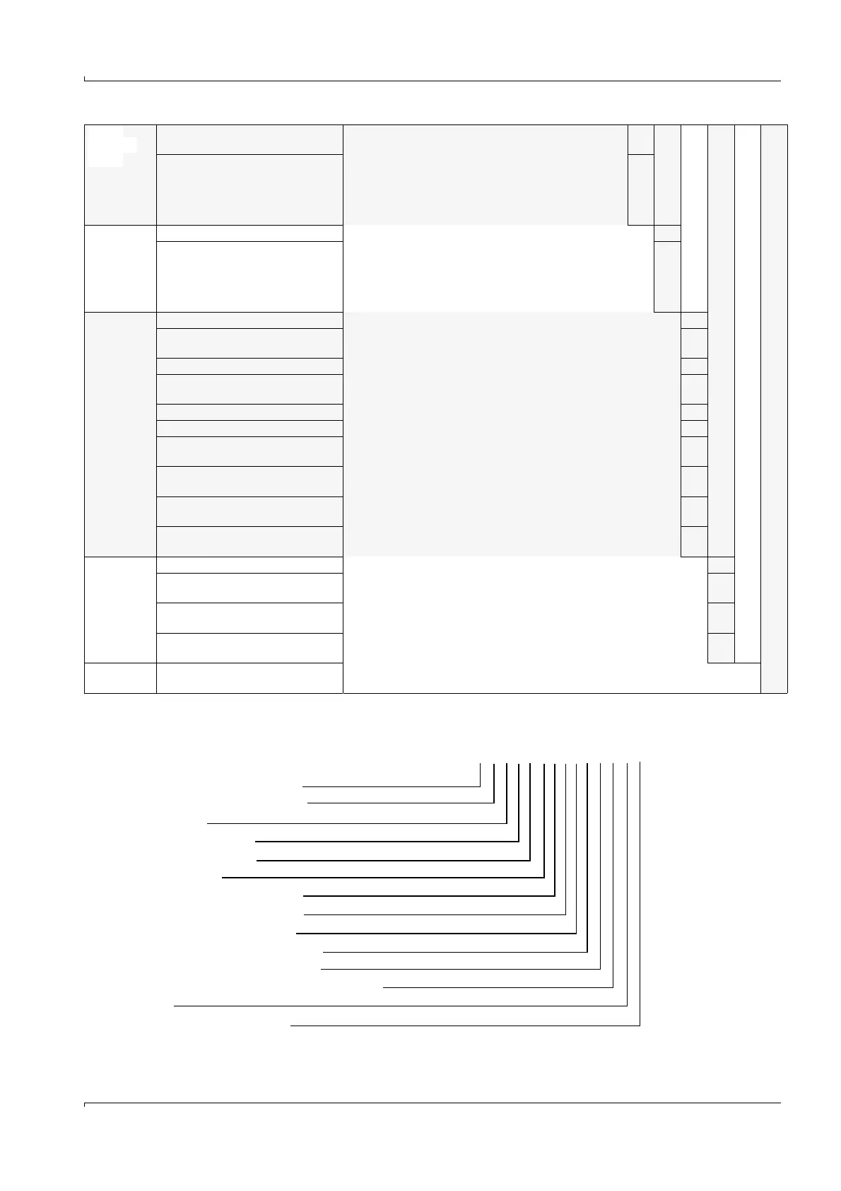
Digital
output W
option
(2 change-
over con-
tacts per
module)
Without optional modules, 5 x relay
contacts on board
0
1 digital output module 1
Digital
output S
option
(4 make-
contacts per
module)
Without optional module 0
1 digital output module
(not yet available)
1
Optional
Interface
module
without interface N
T/P-MOD RS485,MODBUS ASCII/
RTU,pulse
M
T/P-MOD AO,HARTBUS,pulse H
T-MOD CONV HART FF,pulse (on
request)
F
T/P-MOD RS485,PROFIBUS,pulse P
T/P-MOD pulse A
T/P-MOD Ethernet V1,COLA-B, tri-
plex,pulse
V
T/P-MOD Ethernet V2,MODBUS
TCP,pulse
Q
T-MOD CONV IF FF,pulse (on
request)
B
T-MOD CONV IF FF,PID,pulse (on
request)
*
)
C
Remote
Interface
Reserve R
RS485, COLA-B/MODBUS ASCII/
RTU
S
T-MOD Ethernet V2,COLA-B,
Service
W
T-MOD Ethernet V2,MODBUS TCP,
Service
Q
Special
Solution
On request
Example: MCUP-W N D 1 M A 0 1 0 0 0 M R N
Power supply 90 ... 250 V a.c.
no integrated purge air supply
Ex-d housing
one measuring point
metric cable glands
ATEX zone 1 T6
without analog input module
with 1 analog output module
without digital input module
without digital output module W
without digital output module S
Modbus RS485 with pulse output module
reserve
without additional features