58 FLOWSIC100 Flare · Operating Instructions · 8013344/11L2/V 2-5/2018-10 · © SICK Engineering GmbH
Product Description
Subject to change without notice
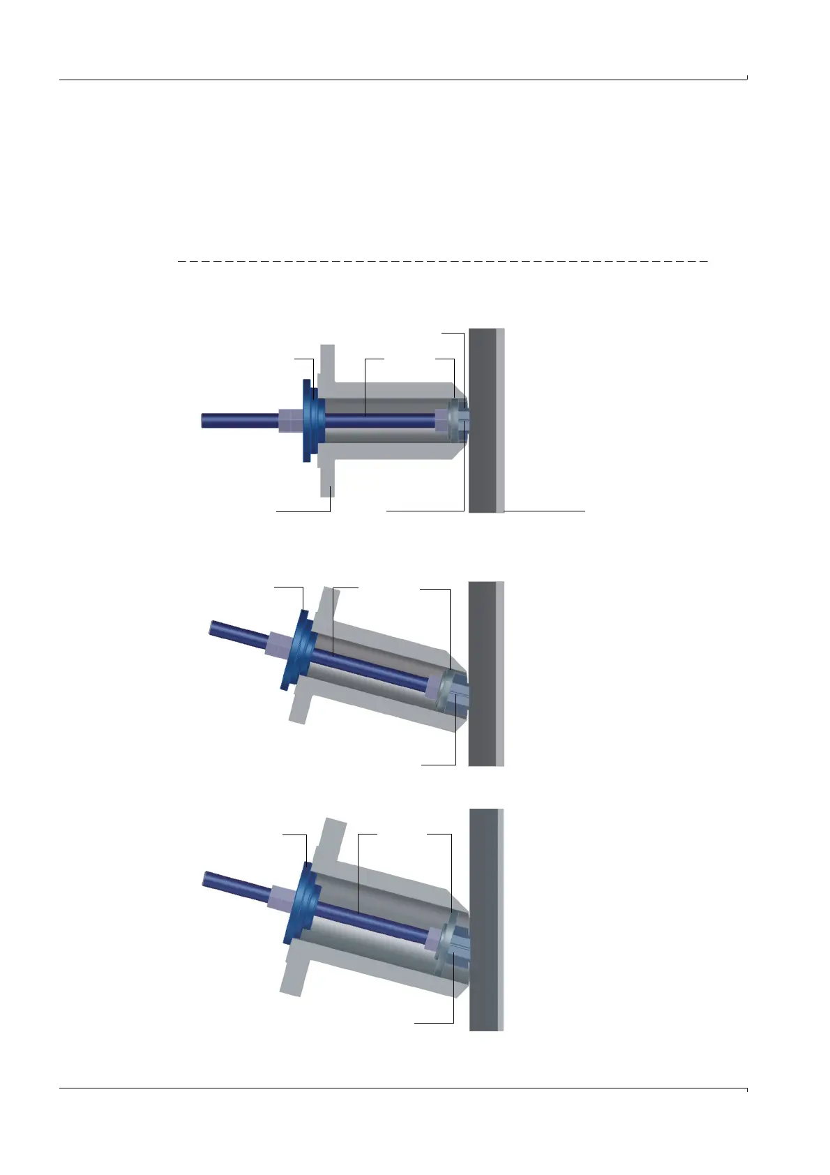
2.2.3 Nozzle installation tool
The installation tool serves to align and weld the nozzle on the pipeline. It consists of:
– welding aid M16 75 °(1) or welding aid M16 90 °(5),
–centering plate 2” (2) or centering plate 3” (6),
– threaded rod M16 length 290 mm (3),
–centering 2”/3” (4),
– installation paper strip as tool to determine the exact nozzle position on the pipeline.
Fig. 24 Nozzle installation tool
Design for FLOWSIC100 EX / EX-RE
Design for FLOWSIC100 EX-PR
Design for FLOWSIC100 EX-S
4 3 2
Nozzle Marking Pipe wall
1