76 FLOWSIC100 Flare · Operating Instructions · 8013344/11L2/V 2-5/2018-10 · © SICK Engineering GmbH
Assembly and Installation
Subject to change without notice
3.1 Project planning
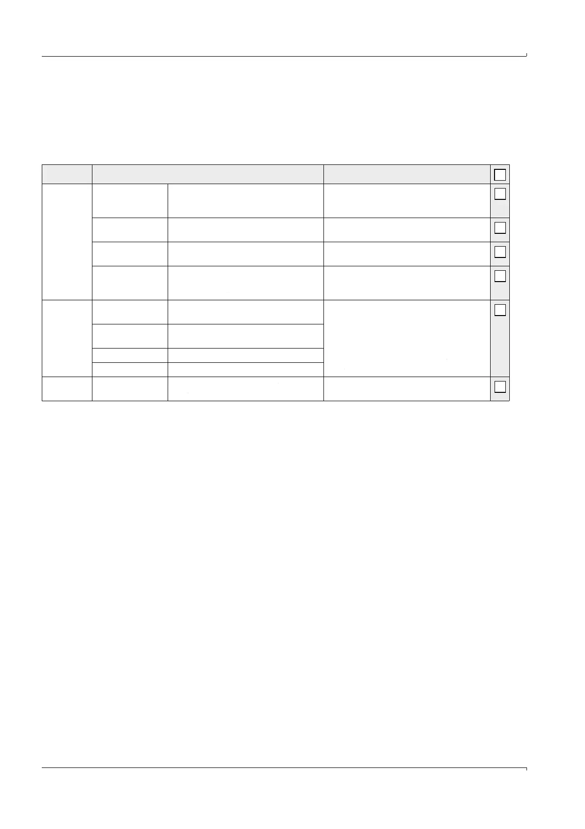
The following table provides an overview of the project planning work necessary as
prerequisite for trouble-free assembly and subsequent device functionality. You can use
this table as a checklist and check off the completed steps.
Ensure that all safety warnings and notes in chapter 1 are observed.
Task Requirements Work step
Determine
measuring
and
installation
locations
(
→
pg. 77,
§ 3.1.1)
Flow distribution,
inlet and outlet
paths
Lowest possible influence on the
measuring precision
Follow specifications for new equipment;
select best possible location for existing
equipment
Access, accident
prevention
Easy and safe Provide platforms or pedestals as required
Installation free of
vibrations Acceleration < 1 g
Eliminate/reduce vibrations through
suitable measures
Ambient conditions
Limit values according to Technical Data in
→
pg. 210, § 6.1
If necessary:
Provide weatherproof covers / sun protection,
enclose or lag device components.
Select
device
components
Internal pipe
diameter
Sender/receiver unit type
Select components according to
Configuration Tables and Notes in
→
pg. 31,
§ 2.2.
Gas temperature
Sender/receiver unit type (standard or
high temperature version)
Gas composition Material of duct probe and transducer
Fitting locations Cable lengths
Plan power
supply
Operating voltage,
power requirements
According to Technical Data in
→
pg. 210,
§ 6.1
Plan adequate cable cross-sections and fuses