Assembly and Installation
FLOWSIC100 Flare · Operating Instructions · 8013344/11L2/V 2-5/2018-10 · © SICK Engineering GmbH 77
Subject to change without notice
3.1.1 Determining the measuring and installation location
Measuring precision is influenced, among other things, by flow behavior and the position of
the measuring axis. Large cross-section variations, curved pipes, fittings, air flaps or inlets
can cause profile deformations or turbulences with a negative effect on the measuring
result.
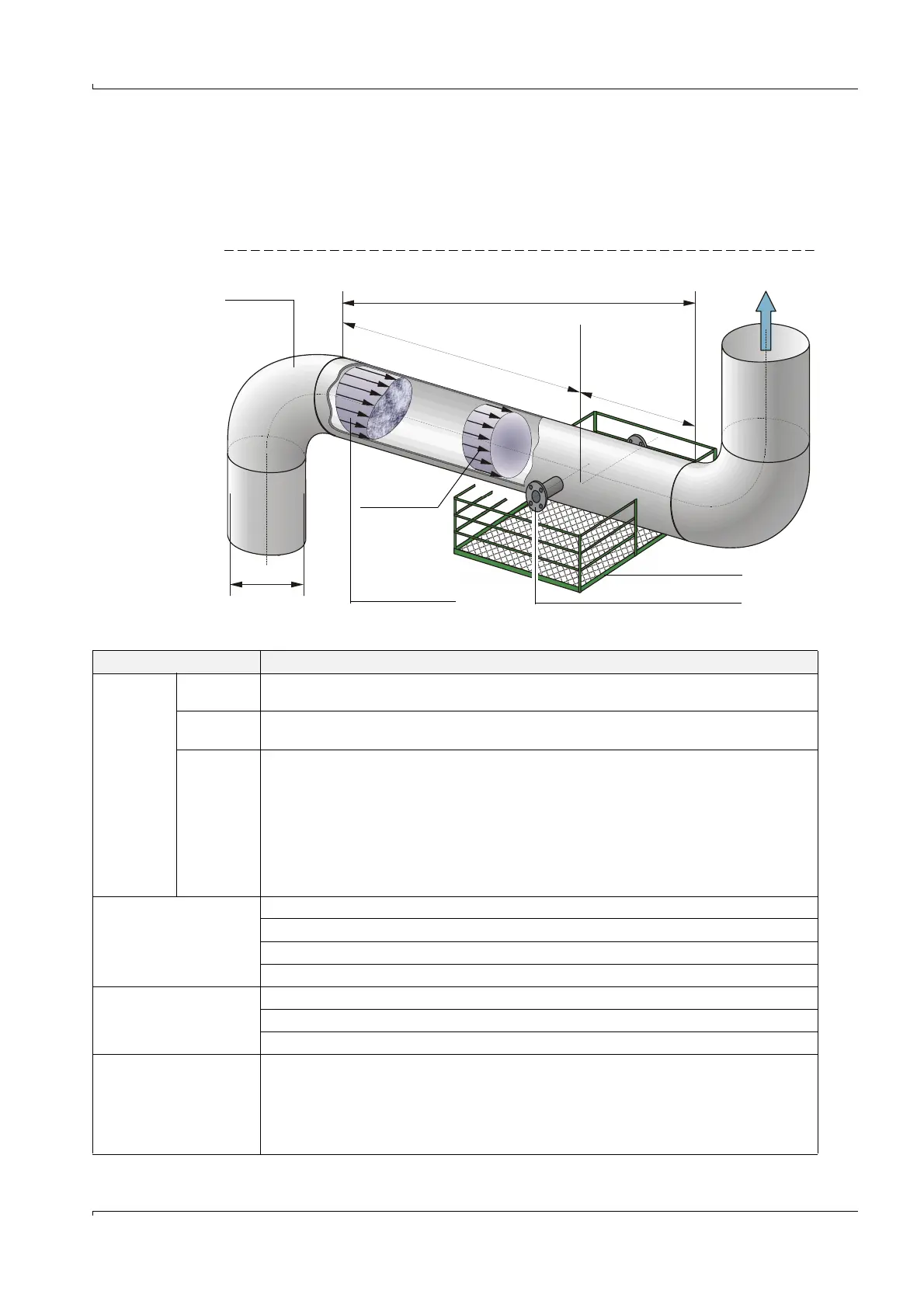
Fig. 30 Measuring and installation location
3.1.1.1 General requirements
Pipeline Possible installation area
Inlet path Outlet path
Di
A
Working platform
Assembly nozzle
10 Di
5 Di
Homogeneous
flow profile
Inhomogeneous
flow profile
Criteria Requirements
Measuring
location
Flow
behaviour
Position with essentially homogenous gas flow
Balanced, uniform profiles are most likely to be expected for long inlet and outlet paths
Pipeline
design
Whenever possible, no deflections, cross-section variations, curves, feed and drain lines, flaps or
fittings in the area of the inlet and outlet paths
Inlet and
outlet path
lengths
Isometric conditions at measuring point are most important for determining the required upstream
and downstream piping and should be investigated carefully.
● Uncritical flow inlet conditions requires straight upstream piping > 10 x Di and downstream
piping > 5x Di. Manufacturer SICK offers expertise support for an optimal adjustment of the
meter for the given inlet and outlet piping conditions.
● More complex inlet disturbances require longer pipings up to 20 Di/10 Di.
● If the 2-path configuration is used, the needed minimum inlet and outlet sections can be further
reduced compared to single path measurement with the same measurement uncertainty.
● For too short inlet/outlet paths: Inlet path > outlet path
Installation location
Pipelines with vertical, horizontal or inclined direction
Installation free of vibrations, acceleration < 1 g
Largest possible distance to control valves or other noisy fixtures
With electrical connections and lighting
Working platform
Easy and safe access for installation and maintenance work of the sender/receiver units
Platform secured by a railing to prevent accidents if necessary
Sufficient clearance to fit/remove the sender/receiver units
Wall and insulation
thickness
● Maximum wall thickness 15 mm, maximum insulation thickness 100 mm.
Larger wall and insulation thicknesses require customer-specific solutions (available on request
only).
● Minimum wall thickness depends on pressure, temperature, pipe size and static/dynamic load
at the measurement location (contact SICK for support).
Nozzles may only be isolated if the gas temperature is < 100 °C.