54 FLOWSIC100 Flare · Operating Instructions · 8013344/11L2/V 2-5/2018-10 · © SICK Engineering GmbH
Product Description
Subject to change without notice
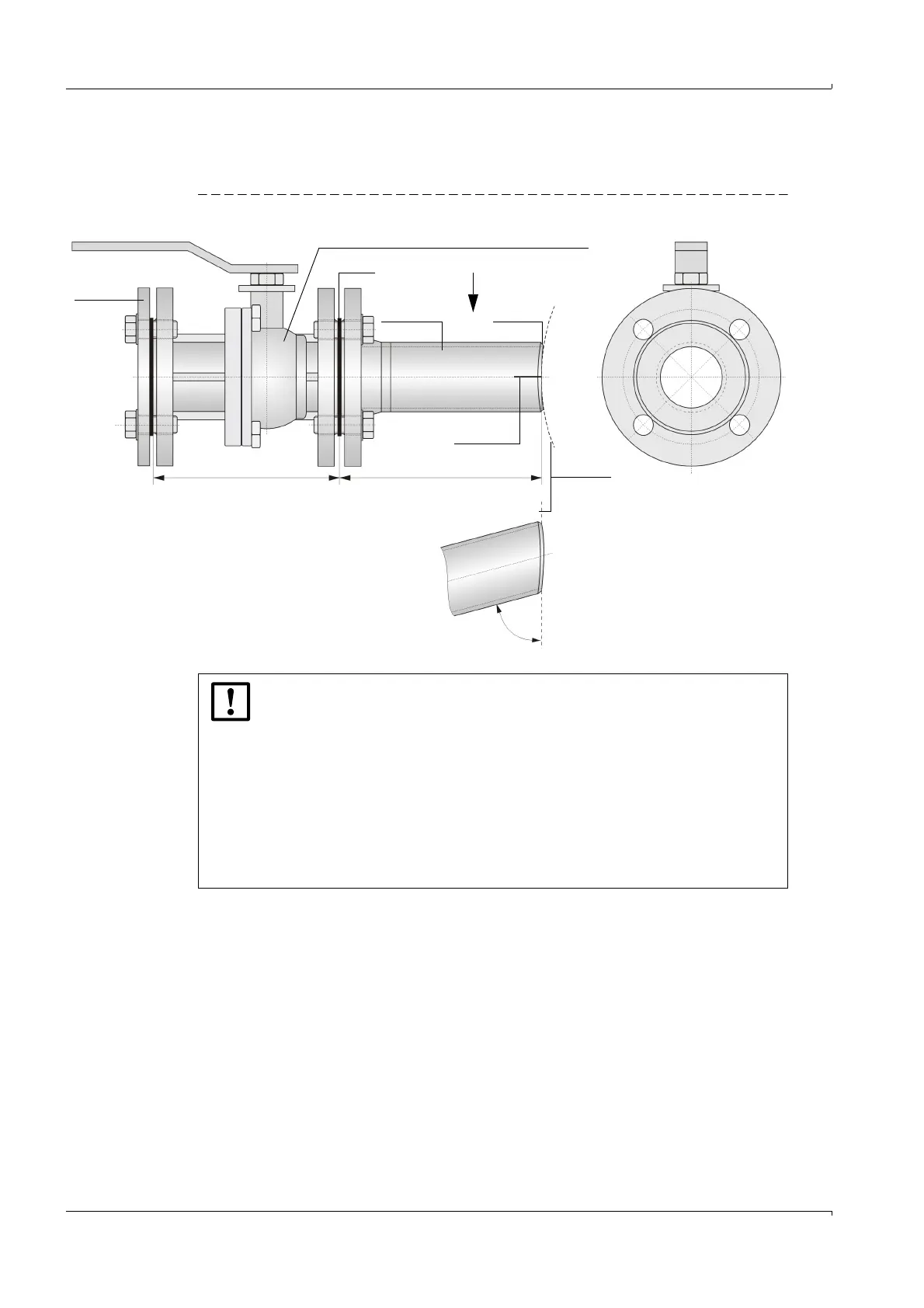
2.2.2 Mounting accessories
Sender/receiver units are fitted to the pipeline using the following material:
Fig. 23 Mounting accessories (according to ANSI CL150; example with nozzle 2" Long Welding Neck")
Blind ( Blind flange
flange not shown)
Ball valve (only for retractable sender/receiver unit)
Seal
Marking
Connection
ANSI CL150 2" or 3”
Path
angle
90 °
View A
for path angle 75 °
75 °
Connection Bevel for
piece welding
VL L (Pipeline)
A
NOTICE:
Use of mounting accessories for standard temperature range -70...+180 C:
● The ball valve must not be insulated for media temperatures below -40 °C
or higher than +160°C.
● For gas temperatures below -40 °C or higher than +180°C, the tempera-
ture at the nozzle flange must be checked after through-heating during ini-
tial start-up. If required, the nozzle insulation must be removed as required
to stay in the specified temperature limit.
● Do not exceed temperature and pressure ranges as listed in
→
p. 55,
2.2.2.1. Material for use outside this specification is available as option
or on request.