64 FLOWSIC100 Flare · Operating Instructions · 8013344/11L2/V 2-5/2018-10 · © SICK Engineering GmbH
Product Description
Subject to change without notice
Type code of Control Unit MCUP
The following type codes define the various configuration options:
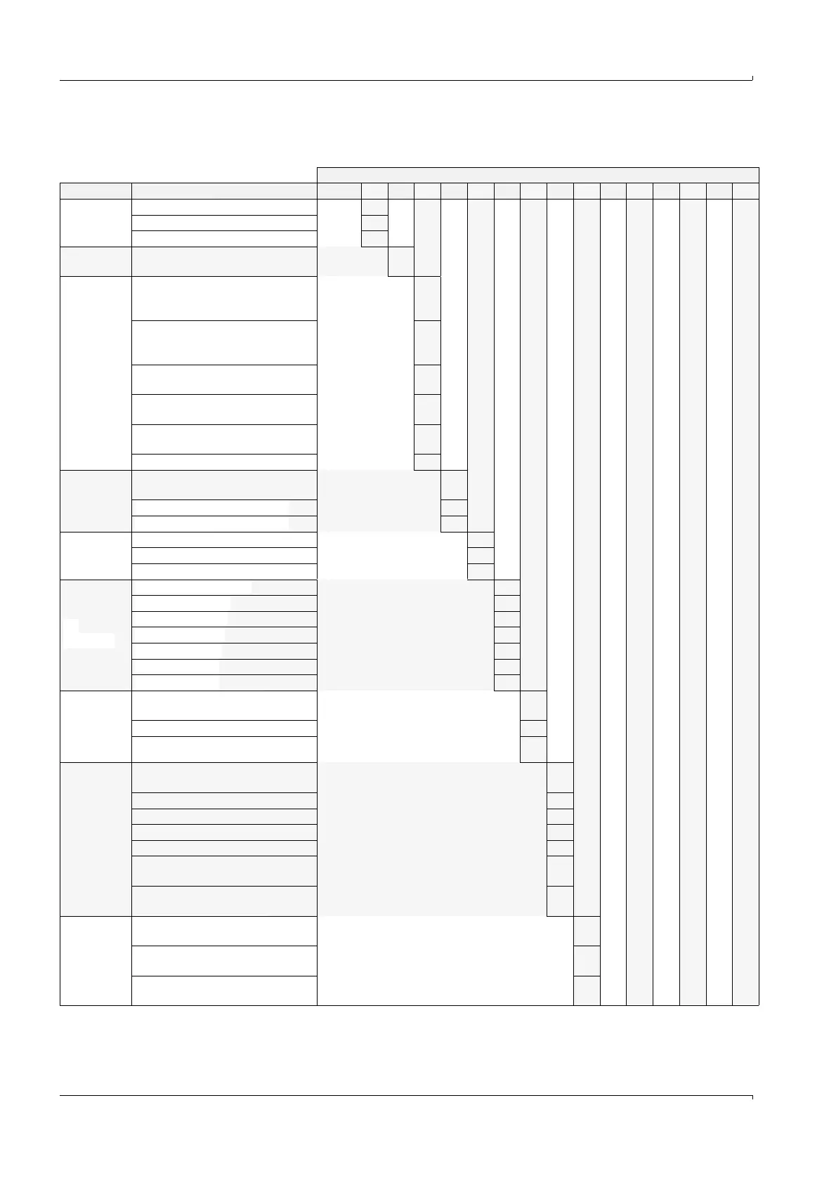
Type code for control unit process
Parameter Design/Description MCUP- X X X X X X X X X X X X X X X
Supply
voltage
90 ... 250 V a.c. W
115/230 V a.c. (zone 2 only) S
Optional 24 V d.c. 2
Purge air
supply
Not integrated N
Case variant
Wall housing Compact, painted,
SICK orange, SS 1.4016 or
equivalent **)
A
Wall housing Medium, painted,
SICK orange, SS 1.4016 or
equivalent, type 4
B
Housing Ex-d/Exe, painted, Al/St,
size 4 (type STAHL) *)
D
Housing Ex-d, painted, Al, size 4
(type STAHL)
K
Housing Ex-d, painted, Al, size 6
(type STAHL)
L
19” rack **) F
Number of
measuring
points
1 measuring point (1x1-path,
1x2-path)
1
2 measuring points (2x1-path) 2
3 measuring points (3x1-path) 3
Housing
cable entry
No cable entries N
Cable entries with metric thread M
Cable entries with NPT thread C
Ex-
protection
without Ex-Certification N
ATEX Zone 1, IIC T6 A
ATEX Zone 2 IIC T4 B
CSA Cl I, Div 1, T6 D
CSA Cl I, Div2, T4 E
INMETRO Zone 1 F
INMETRO Zone 2 G
Analog input
option
(additional
to 2 AI‘s incl.
in standard)
Without optional module,
2 x AI on board
0
1 analog input module 1
2 analog input modules 2
Analog out-
put option
(2 outputs
per module)
Without optional module,
1 x AO on board
0
1 analog output module 1
2 analog output modules 2
3 analog output modules 3
Digital transmitter interface (HART) 5
1 analog input module, digital
transmitter interface (HART)
6
2 analog input modules, digital
transmitter interface (HART)
7
Digital input
option
(4 inputs per
module)
Without optional modules,
2 x DI on board
0
1 digital input module
(not yet available)
1
2 digital input modules
(not yet available)
2