Product Description
FLOWSIC100 Flare · Operating Instructions · 8013344/11L2/V 2-5/2018-10 · © SICK Engineering GmbH 63
Subject to change without notice
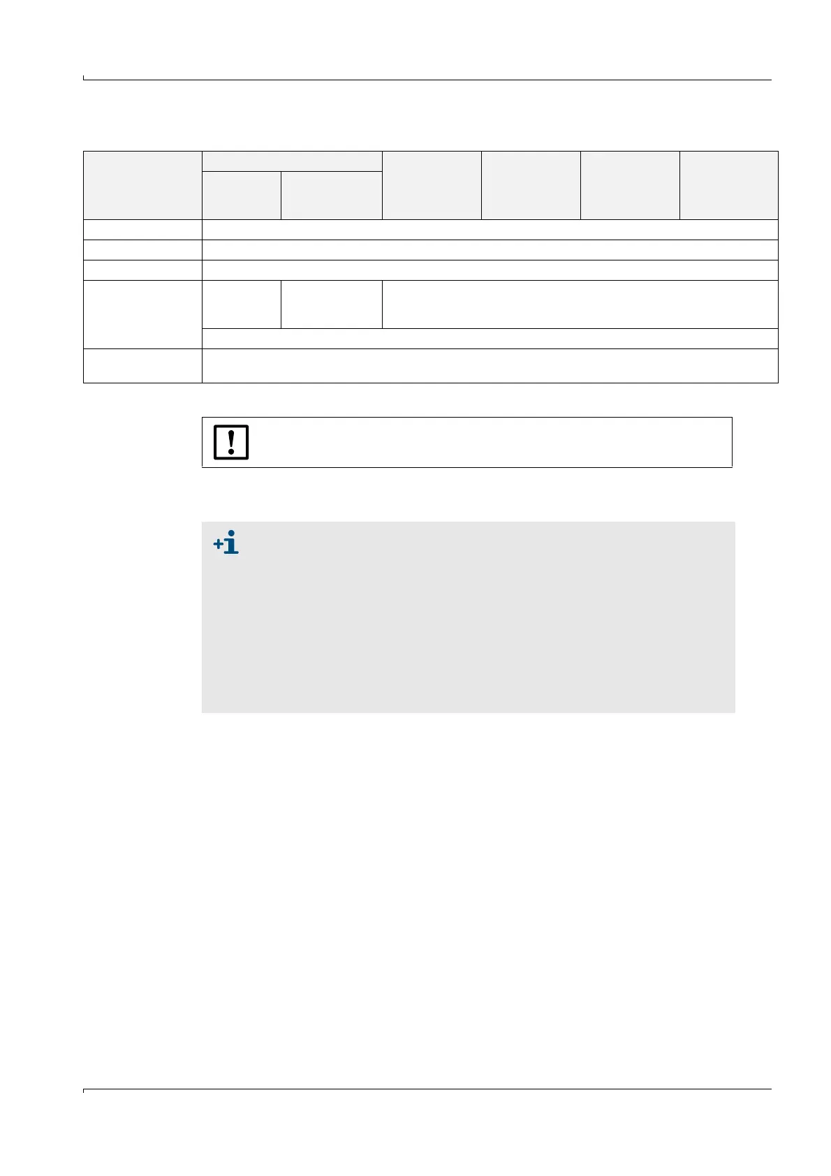
Optional modules
Module carriers (MCUP non Ex with compact or medium housing) have to be positioned on
hat rail (
→
pg. 61, Fig. 25).
Module type
MCUP non Ex MCUP ATEX
Ex zone 2
MCUP ATEX
Ex zone 1
MCUP CSA Cl I,
Div2 / zone 2
MCUP CSA Cl I,
Div1
Compact or
medium
housing
19” rack
Analog output module max. 3 pcs.; with two outputs 0/4 ... 22 mA of each one (max. load 500 Ω)
Analog input module max. 2 pcs.; with two inputs 0/4 ... 22 mA of each one
Digital output module max. 1 pc.; with 2x changeover contacts (load of 30 V a.c./d.c., 5 A; 30 V d.c., 2 A for Ex zone 2)
Accessories required
for analog or digital
modules
1 pc. module
carrier per
module
1 pc. module
carrier 19” for up
to 8 modules
1 pc. module carrier per module
1 pc. connection cable
Interface module
(max. 1 pc.)
Pulse, Ethernet + pulse, Ethernet triplex + pulse, MODBUS TCP + pulse, MODBUS RS485 + pulse,
HARTBUS AO + pulse, PROFIBUS RS485 + pulse, Foundation Fieldbus + pulse
NOTICE:
The maximum number of analog modules is 4.
● Profibus DP-V0 for transmission via RS485 according to DIN 19245, Part 3
as well as IEC 61158.
● The Modbus module supports MODBUS ASCII and MODBUS RTU according
to "Modbus Application Protocol Specification V1.1b".
● Detailed specification for Modbus RS485 and HART® bus modules is con-
tained on the Product CD (can be provided on request before system deliv-
ery).
● The pulse output is part of the interface modules to output the measuring
values for actual volume, standard volume and mass (connection as
"NAMUR" or "Open Collector"
→
pg. 145, Fig. 76; configuration
→
pg. 175,
§ 4.2.6).