166 FLOWSIC100 Flare · Operating Instructions · 8013344/11L2/V 2-5/2018-10 · © SICK Engineering GmbH
Start-up and Parameter Settings
Subject to change without notice
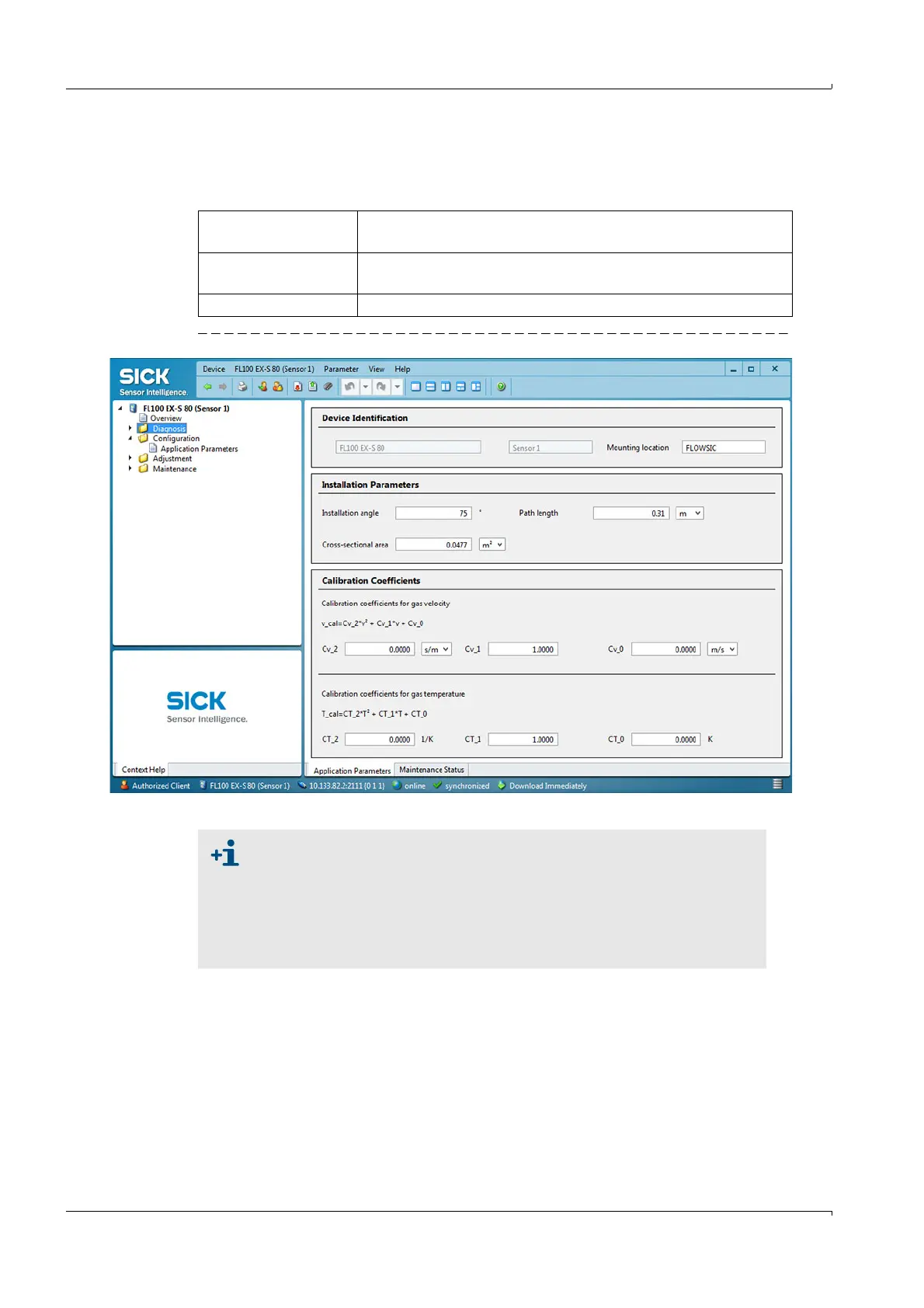
Select the "Configuration / Application Parameter" directory (
→
pg. 166, Fig. 101) and
enter the values determined for path length and angle determined in Section 3.3.1.4 as
well as the cross-sectional area.
Fig. 101 Configuration / Application Parameters" directory (example for settings)
Installation angle Angle between measuring axis and main gas flow direction (path
angle α,
→
pg. 96, § 3.3.1.4)
Path length Distance transducer - transducer (path length L,
→
pg. 96,
§ 3.3.1.4)
Cross-sectional area Internal diameter of the pipeline (
→
pg. 166, Fig. 101)
● The parameters entered are saved in the FLOWSIC100 Flare after the
switching from "Maintenance" to "Measurement".
● Set installation parameters are converted automatically when the unit
of measurement is changed.
● Enter the calibration coefficient for gas velocity Cv_1 ("Calibration Coef-
ficients" group) as a negative value if FLOWSIC100-EXPR is installed at a
vertical pipeline (
→
pg. 81, § 3.1.3).