Assembly and Installation
FLOWSIC100 Flare · Operating Instructions · 8013344/11L2/V 2-5/2018-10 · © SICK Engineering GmbH 131
Subject to change without notice
1)
: normal closed
2)
: normal open
3)
: use only according to consultation with the manufacturer
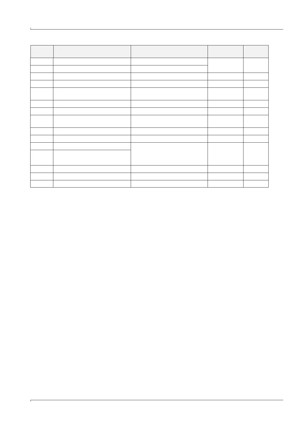
Terminal Marking on the processor board Function Voltage rating
Ampere rat-
ing
25, 26 ain1, gnd Analog input 1
max. 3 V d.c. 22 mA27, 28 ain2, gnd Analog input 2
29, 30 +, gnd Output 24 V d.c. 20 ... 28 V d.c. 3)
31, 32 +24, -24 Power supply bus sender/receiver unit 1 20 ... 28 V d.c.
33, 34 A, B
RS485 interface bus sender/receiver
unit 1
± 5 V
max.
100 mA
35 scr. Screen (gnd)
36, 37 +24, -24 Power supply bus sender/receiver unit 2 20 ... 28 V d.c.
38, 39 A, B
RS485 interface bus sender/receiver
unit 2 ± 5 V
max.
100 mA
40 scr. Screen (gnd)
41, 42 +24 -24 extern Power supply bus sender/receiver units 20 ... 28 V d.c.
43, 45 tx/A, gnd Service interface
– RS232 (non-ex MCUP)
– RS485 (ex-MCUP, option for non-ex
MCUP) - 5 V ... +12 V 3)44, 45 rx/B, gnd
46, 47 + gnd, 24 V in Output 24 V d.c. 20 ... 28 V d.c. 3)
48, 49 + gnd, 24 V Input 24 V d.c. 20 ... 28 V d.c. 3)
P1 P1 service USB Port
 Loading...


