132 FLOWSIC100 Flare · Operating Instructions · 8013344/11L2/V 2-5/2018-10 · © SICK Engineering GmbH
Assembly and Installation
Subject to change without notice
Screen connection of control unit MCUP ATEX zone 1
In a limited number of MCUP ATEX zone 1 units shipped, the shield terminal strip is
electrically isolated from the housing. In this case the shield terminal strip is mounted on
plastic spacers and has no electrical connection to the housing. If in doubt, the isolation
can be checked by a electrical continuity test.
At affected devices the screen of the connection cable between sender/receiver unit and
MCUP can be grounded at MCUP ATEX zone 1 in two ways:
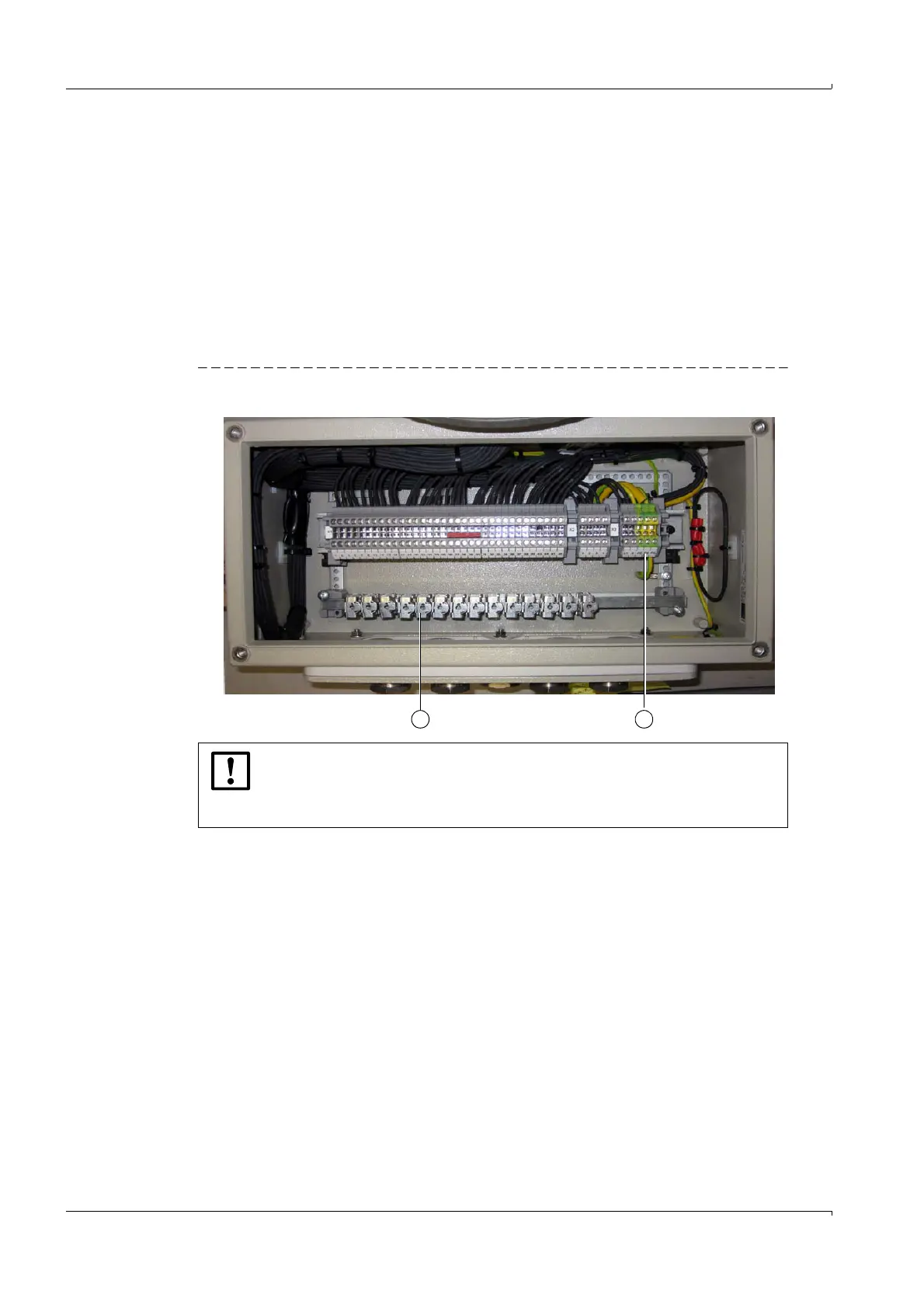
1 Make connection of cable screen at spring-type terminal (1) in the MCUP terminal box.
Connect spring-type terminal strip (1) with PE (2) of the MCUP.
2 Make connection of cable screen at spring-type terminal (1) in the MCUP terminal box.
Connect spring-type terminal strip with external PE at site.
Figure 64 Grounding connection
NOTICE:
Grounding of sender/receiver units has to be established according to
p. 127, § 3.8.4.
The equipotential has to be connected in accordance with IEC 60079-14.